
Hand-Held Power Tool and Method for Operating a Heating Device of a Hand-Held Power Tool

Active Publication Date: 2008-02-14
ANDREAS STIHL AG & CO KG
View PDF13 Cites 11 Cited by
  • Summary
  • Abstract
  • Description
  • Claims
  • Application Information

AI Technical Summary

Benefits of technology

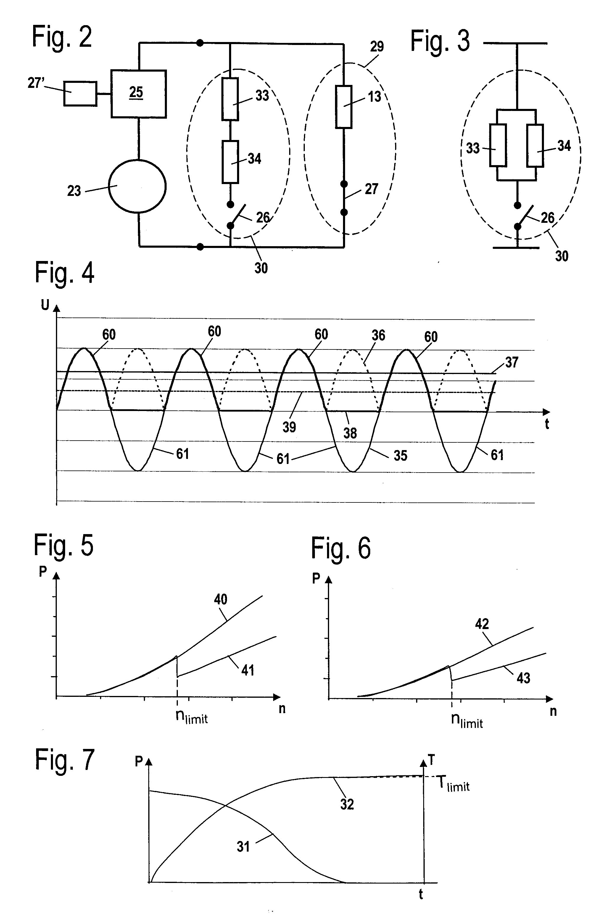
[0007]Expediently, the operating parameter is the engine speed of the drive motor. In this way it is possible to supply the heating element at low engine speed with a sufficiently high power and to lower at high engine speed the power level so that overheating of the heating element is safely prevented. A control of the power depending on the engine speed can be realized in a simple way. Because lowering the power is carried out in the control device, no constructive changes of the power tool are required.
[0008]Advantageously, the heating device has a temperature sensor for a temperature-dependent control of the power supplied to the heating element. In this way, the heating element can be controlled as a function of the engine speed and as a function of the temperature. A simple configuration is provided when the temperature sensor is an NTC (negative temperature coefficient) resistor. Advantageously, the temperature sensor is arranged at a spacing from the heating element. As a result of the spacing between temperature sensor and heating element, the temperature sensor measures the actual heat that is being transferred into the part and not the heat generated at the heating element. As a result of the engine speed-based control of the supplied power, the delay of the temperature measurement that is caused by the spacing between the heating element and the temperature sensor is acceptable because overheating is avoided by an engine speed-based control of the power. As a result of the spacing between the temperature sensor and the heating element, there are more degrees of freedom with regard to the arrangement of the heating element and the temperature sensor which arrangement is usually problematic because of space considerations.
[0009]It is provided that the drive motor is an internal combustion engine with a carburetor and that the heating device is a carburetor heater. In the case of a carburetor heater, overheating is critical in regard to the operation of the internal combustion engine. In particular for a carburetor heater an engine speed-based control of the supplied power is therefore expedient. Advantageously, the temperature sensor is connected by means of a contact surface with the carburetor in a thermally conducting way. In order to eliminate as much as possible effects of the environment on the temperature measurement, it is provided that the temperature sensor has a cover that thermally shields the temperature sensor relative to the environment with the exception of the thermally conducting connection through the contact surface. The temperature sensor measures thus essentially only the heat that is transmitted from the carburetor via the contact surface. The cover is advantageously a cap made from plastic material. Plastic material has satisfactory properties for thermal insulation. A cap made of plastic material can be produced in a simple way and has only a minimal weight. Advantageously, the control device and the temperature sensor are arranged on a common support and the cover is attached to the support by a snap-on connection. The cover provides at the same time a mechanical protection for the control device and the temperature sensor with regard to damage and soiling.
[0013]Advantageously, the operating parameter is the engine speed of the drive motor. The engine speed-dependent control of the power for operating the heating element enables an adjustment of the engine speed-dependent generator power to the heating element. In this way, it can be achieved that sufficient power is available at low engine speed while at higher engine speed an excessive power supply to the heating element is prevented.
[0015]It is provided that the generator generates an alternating voltage signal with which the heating element is operated. Advantageously, a control of the power is realized in that above a limit value every other half wave of the alternating voltage is blocked. The blocked half wave is not used for operating the heating element. Below the limit value, for example, an engine speed limit, each half wave of the induced voltage is transmitted to the heating element. Above the limit value, blocking of every other half wave can be realized by means of an actively controllable element, for example, a thyristor or a triac or a similar device that transmits only positive or only negative half waves to the heating element. In this way, a sufficiently great reduction of the power made available to the heating element can be achieved by simple means. Advantageously, control is done by phase control. In this connection, the engine speed-based control as well as the temperature-based control can be realized by means of blocking every other half wave of the alternating voltage signal and / or by means of phase control.

Problems solved by technology

As a result of the spacing between the temperature sensor and the heating element, there are more degrees of freedom with regard to the arrangement of the heating element and the temperature sensor which arrangement is usually problematic because of space considerations.

Method used


Image

  • Hand-Held Power Tool and Method for Operating a Heating Device of a Hand-Held Power Tool
  • Hand-Held Power Tool and Method for Operating a Heating Device of a Hand-Held Power Tool
  • Hand-Held Power Tool and Method for Operating a Heating Device of a Hand-Held Power Tool

Examples


Embodiment Construction

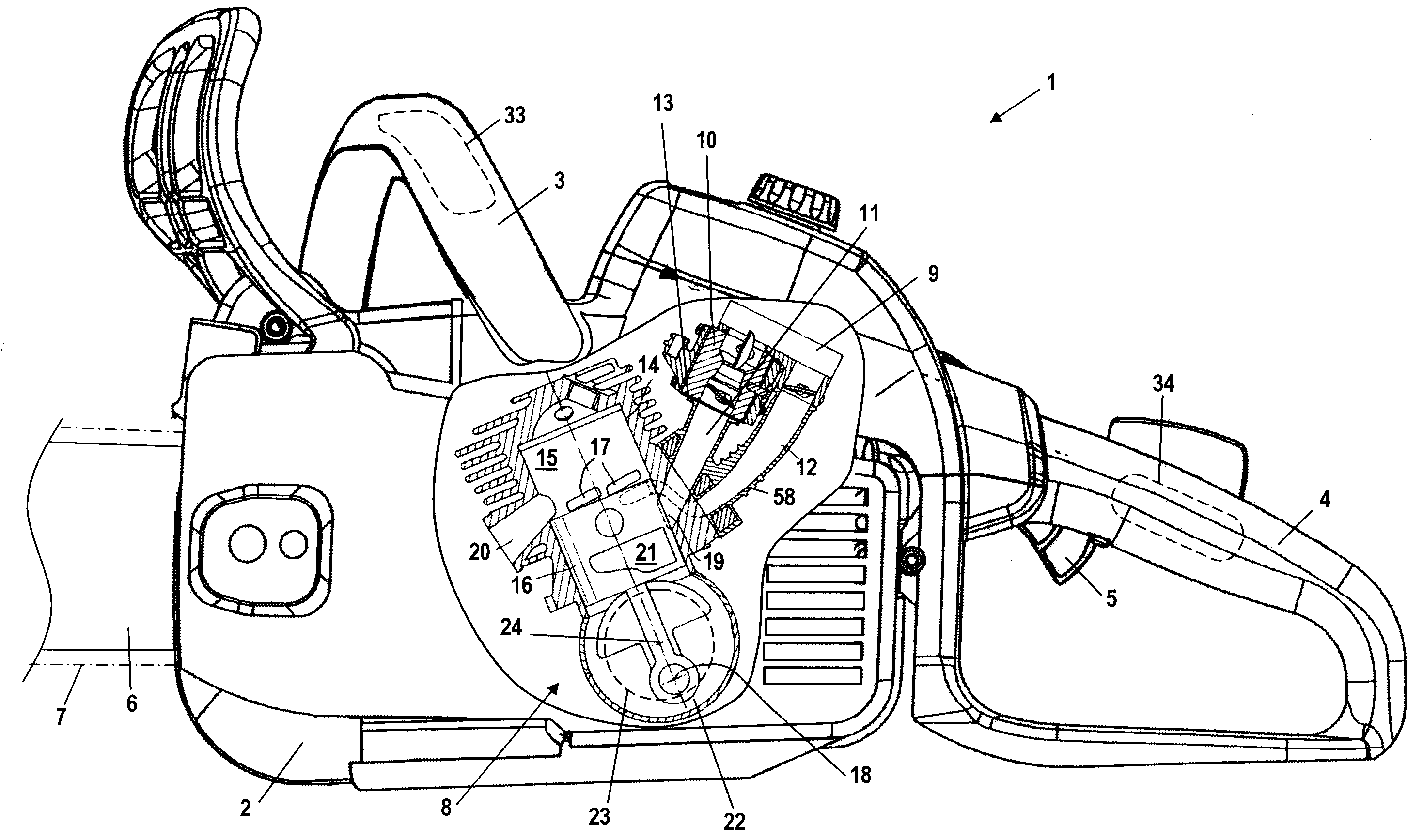
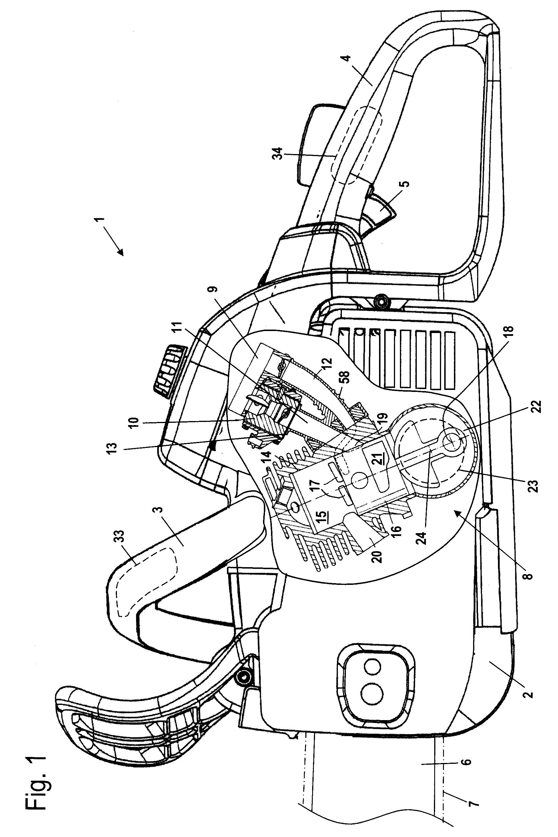
[0034]FIG. 1 shows a hand-held power tool, in this case a motor chain saw 1, in a schematic illustration. The hand-held power tool can also be a trimmer or a similar power tool. The motor chain saw 1 has a housing 2 in which a drive motor 8 is arranged. On the housing 2 a rear handle 4 as well as a grip tube 3 are secured. On the end of the housing 2 opposite the rear handle 4, a guide bar 6 projects from the housing 2 and a saw chain 7 is arranged thereon to circulate thereon. On the rear handle 4, a throttle 5 for operating the drive motor 8 is arranged.

[0035]The drive motor 8 is a single-cylinder two-stroke engine. The drive motor 8 has a cylinder 14 in which a combustion chamber 15 is provided. The combustion chamber 15 is delimited by a piston 16. The piston 16 drives crankshaft 18 about axis of rotation 24, the crankshaft is rotatably supported in crankcase 22. In the area of the bottom dead center of the piston 16 illustrated in FIG. 1, the crankcase 22 and the combustion cha...


PUM

PropertyMeasurementUnit
Temperatureaaaaaaaaaa
Poweraaaaaaaaaa
Speedaaaaaaaaaa

Abstract

A hand-held power tool has a drive motor driving a tool and a generator. One or more heating devices having one or more heating elements are provided. The generator supplies the one or more heating devices with energy. A control device controls a power supplied to the one or more heating elements as a function of at least one operating parameter of the drive motor.

Description

BACKGROUND OF THE INVENTION[0001]The invention relates to a hand-held power tool comprising a drive motor for driving a tool and a generator, wherein the power tool has at least one heating device with at least one heating element and wherein the generator provides the power for operating the heating device. The invention further relates to a method for operating a heating device of a hand-held power tool of the aforementioned kind.[0002]U.S. Pat. No. 6,232,672 B1 discloses a hand-held power tool whose drive motor drives a generator. The generator provides the power for operating a heating device.[0003]The power generated by the generator varies as a function of the engine speed. At low engine speed only minimal power is available; at high engine speed a lot of power is available. The heating element must be designed such that at low engine speed a sufficient heating action is provided so that, for example, in the case of a carburetor heater, freezing of ambient moisture at the carb...

Claims


Application Information

Patent Timeline
IPC IPC(8): F02B63/04H05B1/00
CPCF02M15/04F02B63/02F02B2075/025B27B17/00B25F5/00B27B17/02
Inventor LEUFEN, HEINRICHWALTER, ROLFBERKENKAMP, FRIED
Owner ANDREAS STIHL AG & CO KG
Learn More