Method and device for determining one or more rotational speeds of a turbocharging device, in particular for an internal combustion engine

a turbocharging device and internal combustion engine technology, applied in the direction of electrical control, apparatus for force/torque/work measurement, instruments, etc., can solve the problems of blade deformation of the compressor impeller blade, greater torque and power at the same volume, and greater charge in the combustion chamber, so as to achieve reliable and robust determination of rotational speed

Inactive Publication Date: 2010-12-30
ROBERT BOSCH GMBH
View PDF3 Cites 23 Cited by
  • Summary
  • Abstract
  • Description
  • Claims
  • Application Information

AI Technical Summary

Benefits of technology

[0016]An object of the exemplary embodiments and / or exemplary methods of the present invention is to make available a method and a device for reliable and robust determination of a rotational speed of a turbocharging unit. The object of the exemplary embodiments and / or exemplary methods of the present invention is in particular to make available a method and a device for reliable and robust determination of a rotational speed in a turbocharging unit in a multistage turbocharging system.

Problems solved by technology

The air supplied at a higher pressure in the air system of the internal combustion engine results in a greater charge in the combustion chamber and thus in greater torque and power at the same volume.
The rotational speed is so high at the operating point having a high compression ratio and / or a high volume flow that the centrifugal forces at the circumference of the compressor impeller may result in deformation of the blades of the compressor impeller.
The compressor impeller and other high-speed components of the turbocharger are therefore highly susceptible to wear and material fatigue, so the lifetime of the turbocharger depends on its operating conditions to a great extent.
If the turbocharger is operated near the pumping limit or in the pumping state, the blades of the compressor impeller may be excited to mechanical vibrations, which may cause permanent damage to the compressor impeller if the load is too high or if there is a continuous load.
The vibrations of the blades cause material fatigue more rapidly and ultimately cause fatigue fractures, so that the lifetime of the turbocharger is greatly impaired when pumping states occur.
Frequent operation of a turbocharger at an excessive rotational speed, at which the outer ends of the compressor blades are able to achieve very high velocities, results in a definitely increased material fatigue and thus a reduced lifetime.
Manipulations involving the engine system in particular in tuning the vehicle to increase power may result in the turbocharger frequently being operated at an excessive speed.
This is an abuse of the turbocharger because it significantly shortens its lifetime.
If the turbocharger is defective, the manufacturer incurs high costs, it being difficult to prove abuse.
In addition, wear phenomena occur on the bearings of the turbocharger during operation of the turbocharger, resulting in changes in the uniformity of rotation over the lifetime of the turbocharger.
To take this into account, a safety margin from the maximum allowed rotational speed is usually defined, but this means that the potential of the turbocharger is never fully utilized.
Furthermore, the turbocharger must be designed with larger dimensions so that it has an inferior response in low power ranges, in particular at low engine speeds.
On the other hand, other defects in the engine system may result in failure of the indirect determination of rotational speed as described above.
For example, if a rotational speed of the turbocharger is determined that is too low when a leak occurs downstream from the compressor, thereby increasing the volume flow, but the engine control cannot detect this accurately or at all, depending on the sensor configuration.
In addition, blockage of the air filter may result in a pressure drop upstream from the compressor and thus an increased compression ratio at the same air mass flow and thus result in an increased rotational speed of the turbocharger.
This method of ascertaining the rotational speed has the disadvantage that due to the high temperatures in the compressor, the available sensors are not suitable because they may be sensitive to temperature.
Furthermore, the available installation space on the compressor housing is very limited, so that installation of a corresponding sensor close to the blades of the compressor impeller is limited in particular in small turbochargers.
The adjustment when using the measurement principles mentioned above is also demanding because under some circumstances there are requirements concerning the positioning of the sensor in the submillimeter range.
However, providing individual rotational speed measurements is complex because of the limited installation space and because of the turbocharging devices being situated close to one another locally in such a multistage charging system.

Method used


Image

  • Method and device for determining one or more rotational speeds of a turbocharging device, in particular for an internal combustion engine
  • Method and device for determining one or more rotational speeds of a turbocharging device, in particular for an internal combustion engine
  • Method and device for determining one or more rotational speeds of a turbocharging device, in particular for an internal combustion engine

Examples


Embodiment Construction

[0054]The following specific embodiments are described on the basis of a turbocharger for automotive applications. However, the following description may be applied to any type of compressor in which a medium is drawn in by a compressor impeller using blades and is compressed to a higher pressure.

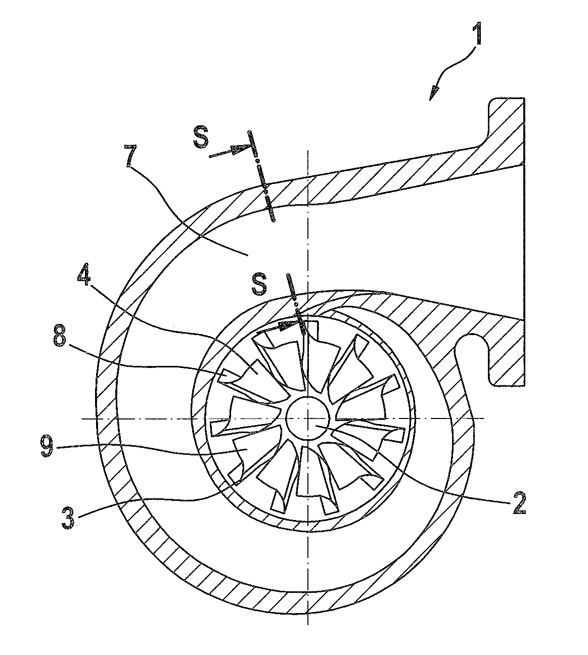
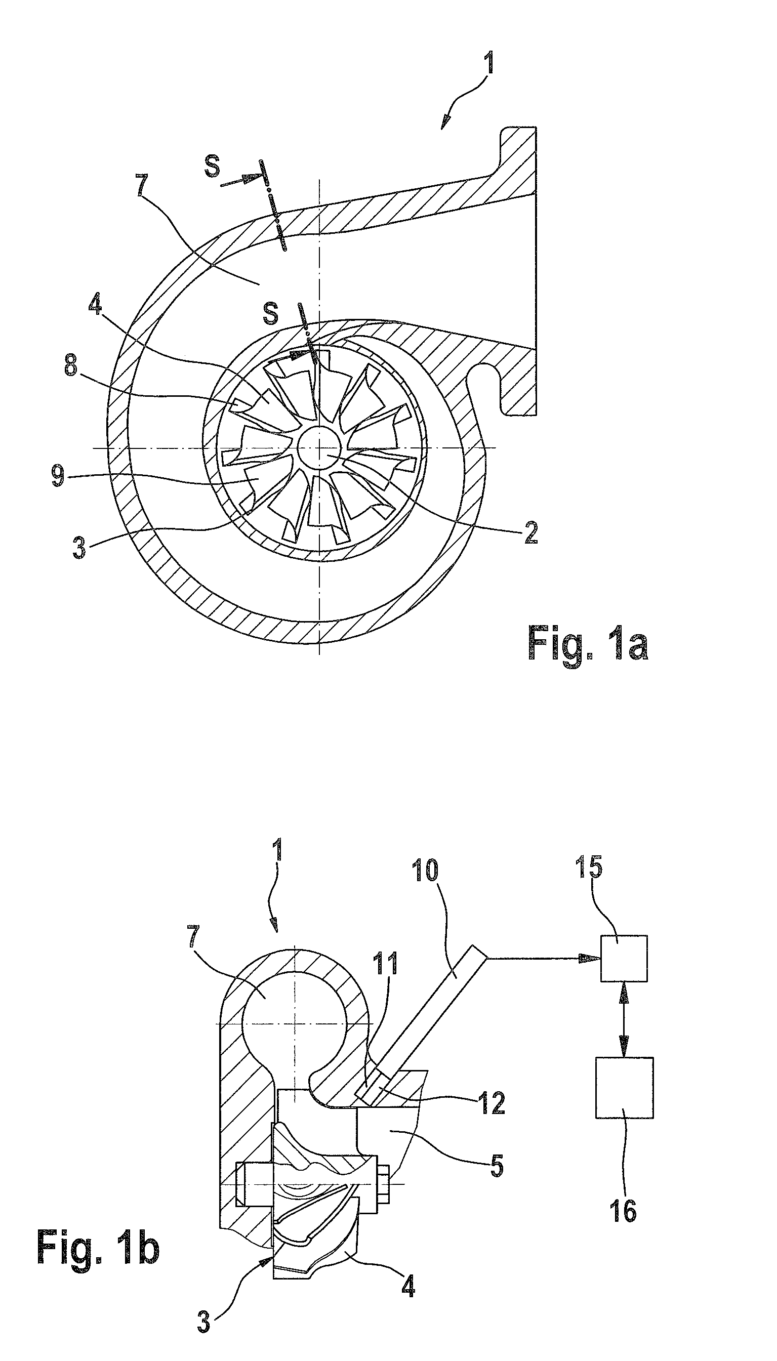
[0055]FIG. 1a shows a cross-sectional diagram through a turbocharger 1 at a right angle to an axial direction of a shaft 2, which is rotatably mounted in a turbocharger housing. FIG. 1b shows a sectional diagram along line S-S of FIG. 1a in the direction of the arrow.

[0056]Turbocharger 1 has a compressor impeller 3 having blades 4 and situated on shaft 2. Air is drawn in via an intake opening 5 in the axial direction of shaft 2 by rotation of compressor impeller 3 in turbocharger 1, is compressed by blades 4 of compressor impeller 3 and ejected via an exhaust port 7, which is situated in a spiral pattern around compressor impeller 3.

[0057]Compressor impeller 3 has a blade web 8 for each bla...


PUM


Abstract

A method is described for determining information about a rotational speed of a compressor, in particular a turbocharger, by providing a measuring signal, in particular a microwave measuring signal, which is directed at a compressor impeller of the compressor, so that the measuring signal is reflected on revolving blades of the compressor impeller, detecting the measuring signal reflected by one or more blades, and determining the information about the rotational speed as a function of the reflected measuring signal.

Description

RELATED APPLICATION INFORMATION[0001]The present application claims priority to and the benefit of German Patent Application No. 10 2009 003 289.4, which was filed on May 20, 2009, German Patent Application No. 10 2009 028 576.8, which was filed on Aug. 17, 2009, and German Patent Application No. 10 2010 003 347.2, which was filed on Mar. 26, 2010, the disclosures of which are incorporated herein by reference.FIELD OF THE INVENTION[0002]The present invention relates to turbocharging devices for internal combustion engines, in particular methods and devices using which one or more rotational speeds of a turbocharging device may be determined.BACKGROUND INFORMATION[0003]Compressors, e.g., turbochargers, are used in motor vehicles for supercharging internal combustion engines to increase power. Turbochargers therefore have a high-speed compressor impeller having blades which draw air in from the environment and feed it at a higher pressure into an air system of the internal combustion ...

Claims


Application Information

Patent Timeline
Patent Type & Authority Applications(United States)
IPC IPC(8): G01M15/04G01P3/00
CPCF02B39/16F02B2039/168Y02T10/144F02D2041/288G01P3/48F02D41/0007Y02T10/12
Inventor SEIDEL, JUERGENGROSSMANN, ALEXOPITZ, BERNHARDHOFMANN, DIRKLAUBENDER, JOCHENKASSNER, UWEEICHEL, DIRKLERCHENMUELLER, KLAUSWENDT, JUERGEN
Owner ROBERT BOSCH GMBH
Why Eureka
Try Eureka