Deadlock detection method and system for parallel programs

a detection method and parallel program technology, applied in the field of parallel programs, can solve the problems of reducing affecting the performance of the algorithm, and the deadlock of the process (thread) is vital, so as to reduce the number of nodes, reduce the complexity of the algorithm, and save time and computing resources.

Inactive Publication Date: 2010-12-30
IBM CORP
View PDF11 Cites 12 Cited by
  • Summary
  • Abstract
  • Description
  • Claims
  • Application Information

AI Technical Summary

Benefits of technology

[0060]With the method and system of detecting deadlocks in parallel programs of the embodiments of the present invention, directed loop detection is performed based on a pruned lock graph to determine whether there is a potential deadlock, which can save a large amount of time and computing resources. Assume that a lock graph of a parallel program has N nodes and E edges, the algorithm of checking direction loop in the lock graph is divided into the following two steps: 1. find all strongly connected components in the lock graph, the complexity of the algorithm is O(N+E); 2. find all directed loops in each of the strongly connected components, the complexity of the algorithm is O(N2). Thus, the complexity of the entire algorithm is O(N2+E). It can be seen that the reduced number of nodes greatly degrades the complexity of the algorithm, and improves the efficiency of deadlock detection.

Problems solved by technology

However, process (thread) deadlock is a vital problem for parallel programs.
Generally, process (thread) deadlock will result in a breakdown of the whole system.
There are a lot of factors that will trigger process (thread) deadlock, mainly including: (1) limited system resource; (2) improper order of processes (threads) execution; and (3) unsuitable resource allocation.
If system resources are abundant and the parallel processes' requests for resources can all be met, the possibility that a deadlock occurs is low.
Otherwise, a deadlock may occur due to competing limited resources.
Further, the order and speed of advancement of process execution is different, which may also cause deadlock.
However, the resources held by T1 or T2 will not be released until the other thread releases its resources, and thus they fall in a deadlock state.
However, in practice, it is not very efficient to apply the above approach in deadlock detection since, as the program runs, more and more nodes and edges are added into the lock graph. FIG. 2 shows an example of a lock graph of parallel programs in which there are 1014 nodes and 3051 directed edges, and the operation of detecting directed loop in the lock graph is very slow, thereby consuming large amounts of time and computing resources, and greatly reducing efficiency of deadlock detection.

Method used


Image

  • Deadlock detection method and system for parallel programs
  • Deadlock detection method and system for parallel programs
  • Deadlock detection method and system for parallel programs

Examples


first embodiment

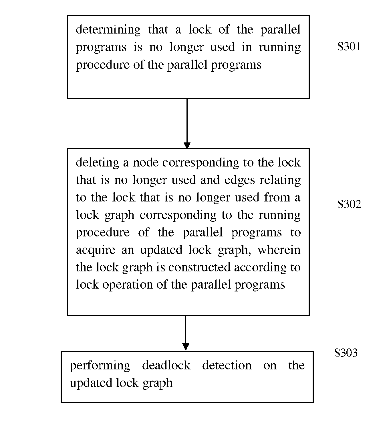
[0033]An example of static code analysis on a c language program example1.c with an explicit function call to destroy a lock is shown below, in which the c language program example1.c contains the mutual exclusive lock Mutex in pthread library of Linux, and a function that destroys the mutual exclusive lock Mutex is: int pthread_mutex_destroy(pthread_mutex_t*mutex); static code analysis needs to scan source code of example1.c without executing the code, identify function code that matches the Mutex destroying function, identify locations that the lock is finally used in the running procedure of parallel programs, and add a mark in the vicinity of these locations to trigger an notification event that the lock is destroyed during running procedure of parallel programs.

1 :#controller thread, named as T12 : #include 3 :4 : pthread_mutex_t list_mutex;5 : pthread_mutex_t request_mutex;6 : pthread_mutex_t control_mutex;7 :8 : void controller_thread( )9 : {10 :  ...11 :   / / create worker_thr...

second embodiment

[0037]An example of static code analysis on a Java language program example2.java without an explicit function call that destroys a lock is shown below.

/ * main in Example2.java * / 01: new T1.start( );02 new T2.start( ); / * Thread 1, named as T1 * / 03: synchronized(G){04:  synchronized(L1){05:   synchronized(L2){ }06:  }07: };08: t3 = new T3( );09: t2.start( );10: t3.join( );11: synchronized(L2){12:  synchronized(L1){ }13: }14: / * Thread 2, named as T2 * / 15: synchronized(G){16:  synchronized(L2){17:   synchronized(L1){ }18:  }19: }20: / * Thread 3, named as T3 * / 21: synchronized(L1){22:  synchronized(L2){ }23: }24:

[0038]There is no explicit function call that destroys locks (G, L1 and L2) in the above example of Java language program, thus it is required to analyze the data stream of parallel programs to determine locations in the parallel programs where the lock is defined and used so as to find a set of locations where the lock may be finally used in the running procedure of parallel pro...

third embodiment

[0049]An example of dynamically analyzing byte code of Java language program Example3.java running on a JVM (Java virtual machine) by using garbage collection is shown below.

/ * main in Example3.java * / 1:2:3: new T1( ).start( ); / / start thread T14:5: T1:6:7: synchronized(G) {8:  synchronized(L1) {9:   synchronized(L2) {10:  }11: }12: new T2( ).start( ); / / start thread T213: ...14: / / lock G is garbage collected at this moment15:16: T2:17:18: synchronized(L1) {19:  synchronized(L2) { }20: }21: ...22 / / lock L1 is garbage collected at this moment

[0050]First, objects of locks G, L1 and L2 that require to be notified when reclaimed by GC are registered on the virtual machine, in response to receiving an event notification issued from JVM that lock G is reclaimed. When the. Java program proceeds to instruction at line 14, it is determined that lock G is no longer used. FIG. 6a shows a lock graph of Java program running on JVM corresponding to the third embodiment, nodes of lock G and edges ...


PUM


Abstract

A deadlock detection method and computer system for parallel programs. A determination is made that a lock of the parallel programs is no longer used in a running procedure of the parallel programs. A node corresponding to the lock that is no longer used, and edges relating to the lock that is no longer used, are deleted from a lock graph corresponding to the running procedure of the parallel programs in order to acquire an updated lock graph. The lock graph is constructed according to a lock operation of the parallel programs. Deadlock detection is then performed on the updated lock graph.

Description

BACKGROUND[0001]1. Field[0002]The present invention relates to parallel programs, more particularly to a deadlock detection method and system for parallel programs.[0003]2. Description of the Related Art[0004]With the rapid development of computer technology, a single-core processor is gradually replaced by a multi-core processor. The multi-core processor significantly improves processing capability and computing capability of a computer, and sufficiently presents the advantage of parallel computing by integrating a plurality of execution cores into one physical processor. So called parallel computing comprises time parallel and space parallel processing, in which the time parallel is related with pipeline technology while the space parallel is related with the parallel technology performed by multiple processors. Generally, parallel computing is implemented by parallel programs in which processing of a task is separated into multiple portions (threads) and these threads can be exec...

Claims


Application Information

Patent Timeline
Patent Type & Authority Applications(United States)
IPC IPC(8): G06F9/46
CPCG06F9/524G06F11/3612G06F11/3604
Inventor LUO, ZHI DAQI, YAOZHENG, YONG
Owner IBM CORP
Why Eureka
Try Eureka