Working machine

a technology for working machines and working parts, applied in the direction of machines/engines, electrical control, exhaust treatment electric control, etc., can solve the problems of reducing the work efficiency of the working machine, deteriorating the reliability of the overall manual regeneration system, and difficult in some cases to install such a warm-up system in the real machine, etc., to achieve short time and simple control

Active Publication Date: 2011-01-06
NIHON KENKI CO LTD
View PDF6 Cites 23 Cited by
  • Summary
  • Abstract
  • Description
  • Claims
  • Application Information

AI Technical Summary

Benefits of technology

[0012]The present invention can perform warm-up in a short time...

Problems solved by technology

However, the above-mentioned patent document does not clearly describe the fact that the warm-up system is preferably configured by what hardware and the fact that the exhaust temperature is preferably increased by what method using the hardware.
For example, if cooling-water temperature rise control using the warm-up system is complicated, it is probable that the reliability of the over...

Method used


Image

  • Working machine
  • Working machine
  • Working machine

Examples


Embodiment Construction

[0020]Embodiments of the present invention will hereinafter be described with reference to the drawings. A description is here given of a case where a manual regeneration system according to an embodiment of the invention is applied to a hydraulic excavator. A hydraulic excavator is one type of a working machine (hydraulic working machine) provided with a hydraulic pump driven by a diesel engine. The hydraulic excavator includes a lower travel structure having a crawler track body; an upper swing body swingably mounted to the lower travel structure; a multi-joint working device mounted to the front of the upper swing body; and a cabin mounted to the upper swing body.

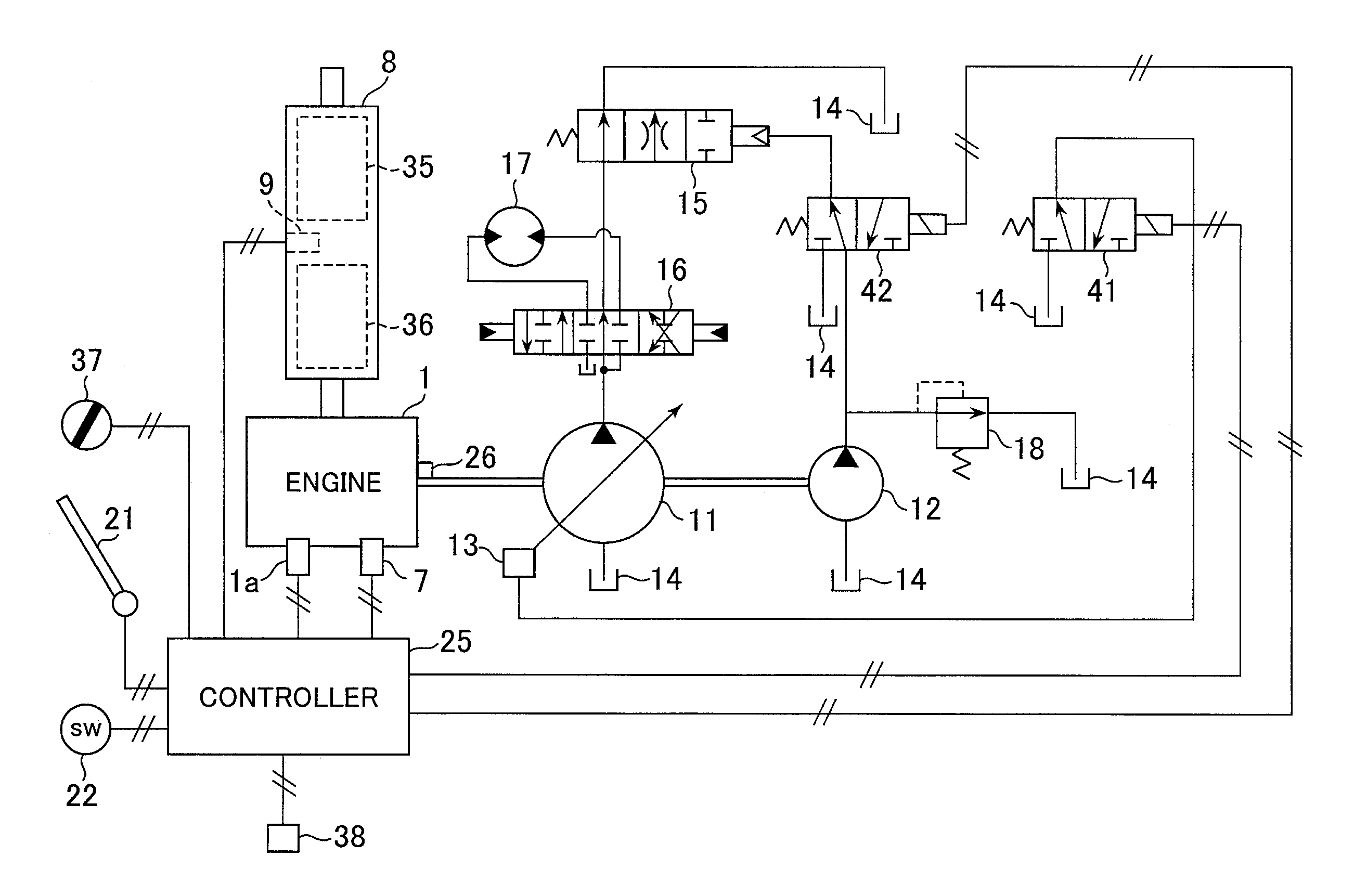
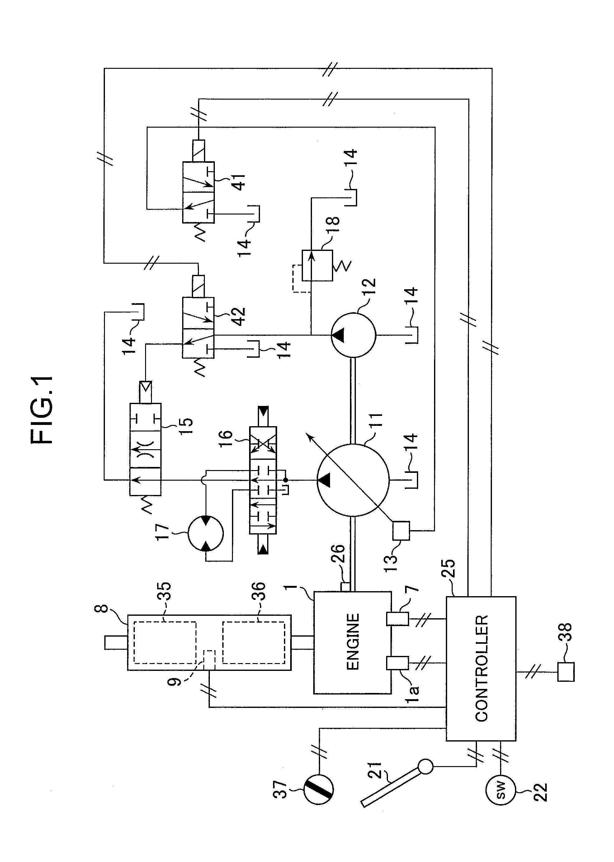
[0021]FIG. 1 is a schematic diagram of a working machine (hydraulic excavator) according to an embodiment of the present invention. The working machine illustrated in the figure includes a diesel engine (hereinafter, abbreviated as “the engine”) 1, exhaust-gas treatment equipment 8, a variable displacement hydraulic pump...


PUM


Abstract

An exhaust gas treatment filter removes particulate matter from exhaust gas of a diesel engine. The particulate matter which accumulates on the filter is removed by a manual regeneration system that can simply be controlled. After a manual regeneration switch 22 is shifted to an ON-position, load control section 66 keeps at least one of the revolution speed N of an engine 1, the displacement volume q and discharge pressure P of a hydraulic pressure pump 11 at a corresponding first target value (N1, q1, or P1) or second target value (N2, q2, or P2) depending on a temperature of the cooling water in relation to a flame-out prevention temperature T1. A regeneration control section 67 starts the compulsory regeneration after the manual regeneration switch has been shifted to the ON-position and when the cooling water temperature is equal to or higher than T0.

Description

BACKGROUND OF THE INVENTION[0001]1. Field of the Invention[0002]The present invention relates to a working machine provided with a diesel engine, a variable displacement hydraulic pump, and exhaust gas treatment equipment.[0003]2. Description of the Related Art[0004]Some exhaust gas treatment equipment removes particulate matter (hereinafter, referred to as PM) from exhaust gas of a diesel engine. Such exhaust gas treatment equipment includes a diesel particulate filter or DPF (hereinafter, abbreviated as “the filter” in some cases). Since this type of exhaust gas treatment equipment has a problem with an increase in discharge pressure, which may occur when PM continuously is accumulated on the filter, it is necessary to remove the PM accumulated on the filter for regeneration of the filter.[0005]The filter is regenerated mainly through self-regeneration or compulsory regeneration. The self-regeneration spontaneously occurs when exhaust temperature reaches a temperature at which PM ...

Claims


Application Information

Patent Timeline
IPC IPC(8): F01N9/00F01N3/025
CPCE02F9/00F01N13/0097E02F9/2246F01N3/103F01N3/106F01N9/002F01N2430/06F01N2430/085F01N2560/06F01N2560/08F01N2590/08F01N2900/1406F01N2900/1602F02D41/0255F02D41/029F02D2041/026Y02T10/26Y02T10/47E02F9/0866E02F9/2066E02F9/2228E02F9/2235Y02T10/12Y02T10/40F01N3/023F01N2260/04
Inventor KAMIYA, SHOHEISATO, KENSUKETSUKADA, HIDENOBUSHIBAMORI, KAZUHIRO
Owner NIHON KENKI CO LTD
Why Eureka
Try Eureka