Hydraulically Locking Stabilizer

a stabilizer and hydraulic technology, applied in the field of downhole drilling operations, can solve the problems of lateral shock and vibration, bit bounce, and temporary lifting off of the drill bit from the formation, and achieve the effects of strong stabilizing force, strong stabilizing force, and minimal frictional losses

Inactive Publication Date: 2011-01-06
SCHLUMBERGER TECH CORP
View PDF39 Cites 9 Cited by
  • Summary
  • Abstract
  • Description
  • Claims
  • Application Information

AI Technical Summary

Benefits of technology

[0013]Exemplary embodiments of the present invention advantageously provide several technical advantages. For example exemplary embodiments of this invention provide a strong stabilizing force between the pressure housing and the drill collar when the downhole tool is deployed in a subterranean borehole. Moreover, the use of radial pistons minimizes frictional losses. The invention also enables easy removal of the pressure housing from the drill collar when the tool has been rem

Problems solved by technology

It is also well known in the art that severe dynamic conditions are often encountered during drilling.
Bit bounce includes axial vibration of the drill string, often resulting in temporary lift off of the drill bit from the formation (“bouncing” of the drill bit off the bottom of the borehole).
Bit bounce, lateral shock and vibration, and stick/slip are commonly recognized as leading causes of electronic failures in downhole tools.
These electronic failures often result in costly trips (tripping the drill string in and out of the borehole) to repair or replace damaged tools and/or tool components.
While such an arrangement tends to adequately centralize the pressure housing(s), the necessary gap between the fins and drill collar tends to damage the inner surface of the collar under vibration and can actually amplify the shock and vibration seen by the electronics.
Moreover, removal of the centralizer can be problematic due to mud packing between the ring and collar ID.
However the screws have been known to loosen in service thereby unlocking the device and allowing motion of the device due to the downhole dynamic conditions.
The screws have even been known to completely unscrew and fall down through the BHA t

Method used


Image

  • Hydraulically Locking Stabilizer
  • Hydraulically Locking Stabilizer
  • Hydraulically Locking Stabilizer

Examples


Embodiment Construction

[0025]Referring first to FIGS. 1 through 6, it will be understood that features or aspects of the exemplary embodiments illustrated may be shown from various views. Where such features or aspects are common to particular views, they are labeled using the same reference numeral. Thus, a feature or aspect labeled with a particular reference numeral on one view in FIGS. 1 through 6 may be described herein with respect to that reference numeral shown on other views.

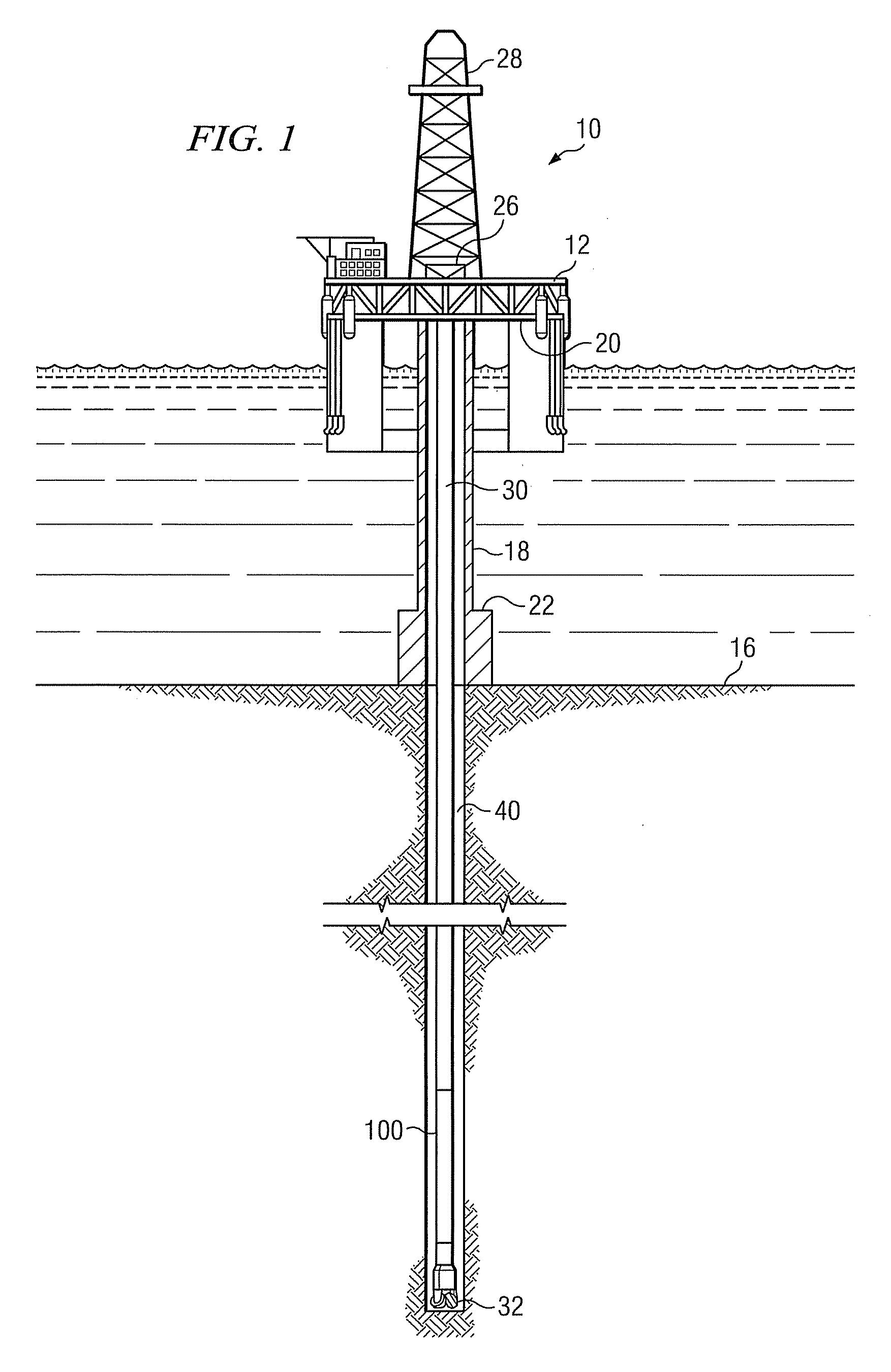
[0026]FIG. 1 illustrates a drilling rig 10 suitable for the deployment of exemplary embodiments of the present invention. In the exemplary embodiment shown on FIG. 1, a semisubmersible drilling platform 12 is positioned over an oil or gas formation (not shown) disposed below the sea floor 16. A subsea conduit 18 extends from deck 20 of platform 12 to a wellhead installation 22. The platform may include a derrick 26 and a hoisting apparatus 28 for raising and lowering the drill string 30, which, as shown, extends into borehole...


PUM


Abstract

A downhole tool includes a pressure housing deployed in the bore of a drill collar. At least three fins are deployed on the housing and in the tool annulus. At least one of the fins includes a floating blade deployed thereon. The blade includes a plurality of radial pistons deployed therein. The pistons are configured such that the surface area of the radially outward facing piston surfaces is greater than the surface area of the radially inward facing piston surfaces. This piston configuration causes the surface area of the radially outward facing blade surface to be less than the radially inward facing blade surface. In operation, hydrostatic pressure exerts a differential force on the pistons and the floating blade thereby urging the pistons radially inward towards the housing and the blade radially outward towards the drill collar.

Description

RELATED APPLICATIONS[0001]None.FIELD OF THE INVENTION[0002]The present invention relates generally to downhole drilling operations and in particular to an apparatus for stabilizing and / or centralizing a pressure housing in a drill collar.BACKGROUND OF THE INVENTION[0003]In recent years there has been a marked increase in the sophistication of downhole tools, and in particular, downhole tools deployed in the bottom hole assembly (BHA) of a drill string. A typical BHA commonly includes, for example, one or more logging while drilling (LWD) and / or measurement while drilling (MWD) tools. Such tools are well known to include various electronic sensors such as gamma ray sensors, neutron sensors, resistivity sensors, formation pressure and temperature sensors, ultrasonic sensors, audio-frequency acoustic sensors, magnetic sensors, acceleration sensors, and the like. LWD and MWD tools typically further include an electronic controller including at least one microprocessor and electronic mem...

Claims


Application Information

Patent Timeline
IPC IPC(8): E21B17/10
CPCE21B17/1014E21B17/1007E21B23/04E21B47/01E21B23/0422
Inventor CHESNUTT, DENNIS PATRICK
Owner SCHLUMBERGER TECH CORP
Why Eureka
Try Eureka