Mixer-transconductance interface

Inactive Publication Date: 2011-01-06
QUALCOMM INC
View PDF17 Cites 4 Cited by
  • Summary
  • Abstract
  • Description
  • Claims
  • Application Information

AI Technical Summary

Benefits of technology

Yet another aspect of the present disclosure provides an apparatus comprising: a mixer block coupled to a first input voltage, the mixer block comprising a plurality of mixer unit cells each coupled to the first input voltage and to a corresponding mixer unit input current, at least one mixer unit cell capable of being selectively enabled or disabled, each mixer unit cell configured to generate an output signal proportional to the first input voltage mixed with the corresponding mixer unit input current; a transconductance (Gm) block coupled to a second input voltage, the Gm block comprising a plurality of Gm unit cells each coupled to the second input voltage, at least one Gm unit cell capable of being selectively enabled or disabled, each Gm unit cell configured to generate at least one Gm unit output current proportional to the second input voltage; and means for efficiently coupling the Gm unit output currents to the mixer unit input currents.

Problems solved by technology

The amount of added circuitry required to support multi-mode and complex operation may unacceptably increase the integrated circuit (IC) die area, as well as increase the number of signal leads in the interface between the mixer and the Gm block.

Method used


Image

  • Mixer-transconductance interface
  • Mixer-transconductance interface
  • Mixer-transconductance interface

Examples


exemplary embodiment 300

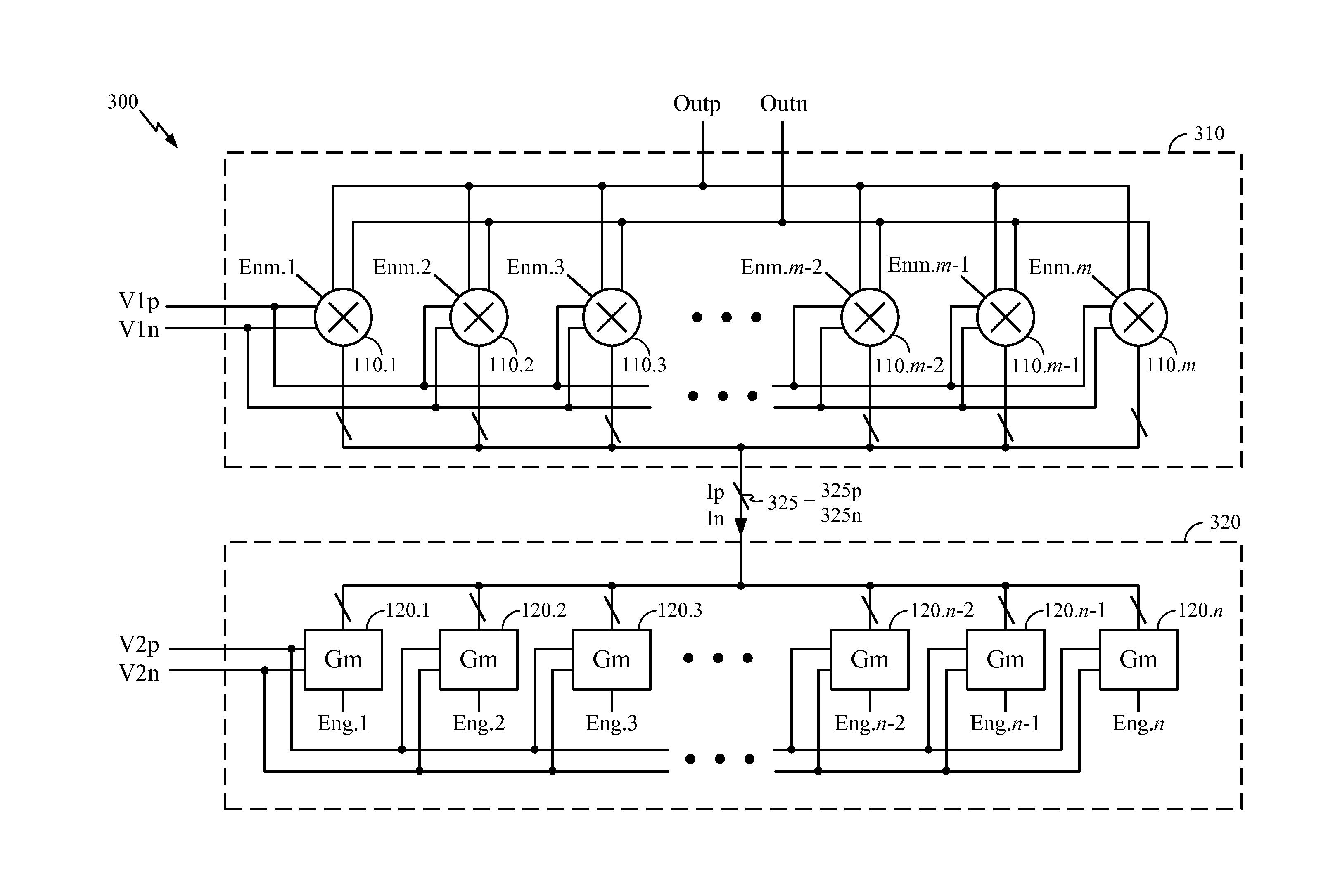
FIG. 3 illustrates an exemplary embodiment 300 of a gain-controlled mixer-transconductance block according to the present disclosure. In FIG. 3, the Ip outputs of the n Gm unit cells 120.1 through 120.n are conductively coupled together, and the In outputs of the n Gm unit cells are also conductively coupled together. In this specification and in the claims, the term “conductively coupled” shall denote the condition wherein an electrical short circuit, i.e., a conductive path of low electrical resistance, exists between the coupled nodes.

The sum of the Ip currents is carried on a single conductive lead 325p, and the sum of the In currents is carried on a single conductive lead 325n. The two conductive leads 325p and 325n are collectively labeled as the conductive path 325 in FIG. 3. At the mixer, the leads 325p and 325n are each coupled to the individual current inputs of the mixer unit cells 110.1 through 110.m. The conductive leads 325p and 325n may be understood as being fanned o...

exemplary embodiment 400

In an exemplary embodiment, the techniques described herein may further accommodate transceivers utilizing a quadrature mixing scheme. FIG. 4 illustrates an exemplary embodiment 400 of a mixer-transconductance block for mixing two complex signals with each other. In FIG. 4, the mixer-transconductance block 400 is configured to mix in-phase and quadrature differential local oscillator voltages (LO_Ip, LO_In, LO_Qp, LO_Qn) with in-phase and quadrature differential voltages (V_Ip, V_In, V_Qp, V_Qn) corresponding to a received signal or signal to be transmitted. Note in FIG. 4 that the enable signals for the mixer unit cells (not shown) are labeled Enm.1 . . . . Enm.m (I) for the in-phase voltages and Enm.1 . . . Enm.m (Q) for the quadrature voltages, while enable signals for the Gm unit cells (also not shown) are labeled Eng.1 . . . Eng.n (I) for the in-phase voltages and Eng.1 . . . Eng.n (Q) for the quadrature voltages.

In the embodiment 400, separate conducting paths are provided to ...


PUM


Abstract

Techniques for providing an efficient interface between a mixer block and a transconductance (Gm) block. In an exemplary embodiment, the output currents of at least two unit cells of the transconductance block are conductively coupled together, and coupled to the mixer block using a single conductive path. For a differential signal, the conductive path may include two conductive leads. Within the mixer block, the single conductive path may be fanned out to at least two unit cells of the mixer block. At least one Gm unit cell may be selectively enabled or disabled to control the gain setting of the mixer-transconductance block. The techniques may further be applied to transceiver architectures supporting in-phase and quadrature mixing, as well as multi-mode and / or multi-band operation.

Description

BACKGROUND1. FieldThe disclosure relates to circuit design, and in particular, to an efficient mixer-transconductance interface.2. BackgroundCommunications circuitry may employ one or more mixer circuits to translate a signal spectrum from one frequency to another frequency. For example, in a transmitter, a mixer may be used in an upconverter to convert a baseband signal to a radio-frequency (RF) signal. In a receiver, a mixer may be used in a downconverter to convert a received RF signal to an intermediate frequency (IF) or baseband for processing. Certain mixer circuits may utilize a current-mode architecture wherein a first input voltage is mixed with a signal current, e.g., a bias current of the mixer, to generate an output signal. The signal current may be generated by a transconductance (Gm) block, which in turn generates the signal current from a second input voltage. In some implementations, both the mixer and the Gm block may be provided with multiple gain settings to tune ...

Claims


Application Information

Patent Timeline
IPC IPC(8): G06G7/12
CPCH03D7/165
Inventor CHOKSI, OJAS M.RANJAN, MAHIM
Owner QUALCOMM INC
Why Eureka
Try Eureka