Laser confocal scanning microscope and methods of improving image quality in such microscope

a scanning microscope and laser confocal technology, applied in the field of laser confocal scanning microscope and methods of improving image quality in such microscopes, can solve the problems of reducing the overall efficiency of the system by half, random striping, and complicating the production of such configurations, so as to reduce striping and reduce striping. , the effect of increasing throughpu

Inactive Publication Date: 2011-01-06
VISITECH INT LTD
View PDF11 Cites 10 Cited by
  • Summary
  • Abstract
  • Description
  • Claims
  • Application Information

AI Technical Summary

Benefits of technology

[0018]The present invention provides a laser confocal scanning microscope and methods of achieving increased throughput and reduced striping due to imperfections in the microlens and / or confocal aperture arrays, of achieving reduced striping and of achieving selectable degrees of confocality.
[0019]The present invention accordingly provides a laser confocal scanning microscope comprising a laser light source for emitting laser light at one or more different wavelengths; a laser beam expander for expanding the laser beam; a first galvanometer mirror for scanning and directing the laser light beam into a scanned sample plane via a microscope and for de-scanning a return light from the scanned sample plane; an array of microlenses positioned between said laser beam expander and said first galvanometer mirror, constructed and orientated such that a single scan of the first galvanometer mirror causes each microlens of the array to trace a separate scan line across the sample plane; an array of confocal apertures, which duplicates the pattern position of said array of microlenses pre-aligned such that each confocal aperture coincides with the matching microlens in said array of microlenses; a dichromatic mirror or a beam splitter, positioned between said first galvanometer mirror and said array of microlenses for separating the return light from the incident light path and directing the return light to said array of confocal apertures; an image detector, wherein the arrangement of said array of confocal apertures and of said first galvanometer mirror is such that light transmitted by said array of confocal apertures is directed to the rear face of said first galvanometer mirror, which is also a mirror, and as a result is scanned into said image detector; a means for driving said first galvanometer mirror to scan the laser light beam emerging from said array of microlenses over the sample plane, to descan the returned light from the sample plane, and to rescan the light passing through said confocal apertures into said image detector; and one or more of the following elements: a means to modify the illumination intensity distribution over the sample scanning beams, a means to modify the coherency in the sample scanning beams, a means to reduce variations in the illumination intensity distribution in the sample plane, and a means to modify the confocality of the scanned image.
[0020]The present invention also provides a method of increasing the intensity throughput of a laser confocal scanning microscope and reducing the appearance of ‘stripes’ due to imperfections in a microlens array and / or confocal aperture array thereof, comprising increasing a number of repeat patterns in the microlens and confocal aperture arrays that are scanned over an image (and sample) plane for each captured image, and controlling an emitted laser beam intensity to maintain constant integrated intensities in an image detector while the bidirectional scanning system changes direction.
[0021]The present invention further provides a method of reducing striping in the images captured by a laser confocal scanning microscope, comprising adding a second galvanometer mirror such that a Gaussian intensity distribution of an emitted laser light is de-scanned at an image (and sample) plane, and / or destroying coherency of an emitted laser light beam by inserting a small angle diffuser, and / or flattening of a Gaussian intensity profile of an emitted laser light beam.

Problems solved by technology

Thus the laser illumination is only present in the field of view for half of the total scan duration, reducing the overall efficiency of the system by half.
Each microlens and confocal aperture pair creates a single scanning line across the image (and sample), and due to the single repeat pattern of both the microlens and confocal aperture arrays, defects in a single microlens or single confocal aperture become evident in the captured images as a darker or brighter scan line than the immediate neighbours, giving rise to random ‘striping’.
In the selectable pinhole assembly the oil (optical fluid) required to lubricate the sliding plates (to prevent scratching of their surfaces) should match the refractive indices between the sliding plates of the selectable confocal apertures and this complicates the production of such a configuration and it is also liable to failure of the sealing components.

Method used


Image

  • Laser confocal scanning microscope and methods of improving image quality in such microscope
  • Laser confocal scanning microscope and methods of improving image quality in such microscope
  • Laser confocal scanning microscope and methods of improving image quality in such microscope

Examples


Embodiment Construction

[0036]Preferred embodiments of the present invention are now described by reference to the drawing.

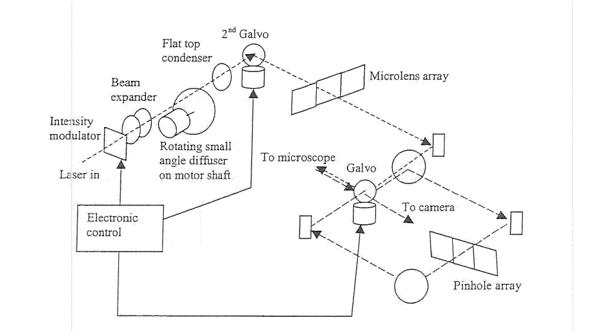
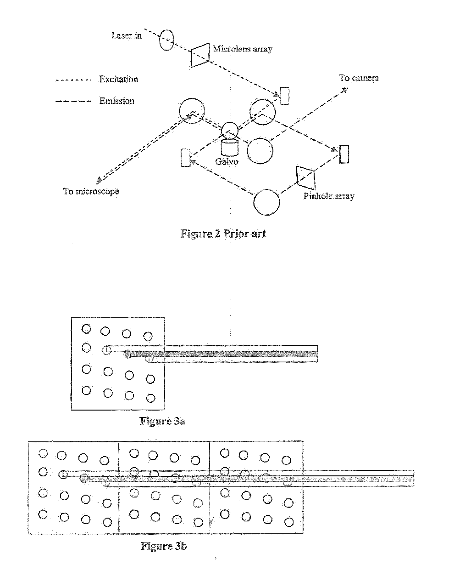
[0037]A first feature overcomes the lower throughput efficiency and reduces the random ‘striping’ due to imperfections in the microlens or aperture arrays of a 2-D array laser confocal scanner 10. This design requires additional scan patterns to be incorporated into a microlens array 12 and scanned by a galvanometer mirror 14 coupled to a motor 15 and a control 16. These additional repeat patterns along the axis of the scanning direction permit the scanning process to scan across the sample without the ‘dead’ time inherent in the original design. The patterns are arranged such that the patterns at each end of the array are fully superimposed over the field of view when the galvanometer mirror changes its scan direction. Thus it becomes possible to continuously illuminate the sample during the scanning process, without ‘dead’ time (compare FIG. 4 and FIG. 5a).

[0038]With continuous illum...


PUM


Abstract

According to a first embodiment the invention provides for increasing the throughput and reducing the striping due to imperfections in the microlens and / or confocal aperture arrays of a Laser Confocal Scanning Microscope by increasing the number of repeat patterns in the microlens and confocal aperture arrays to more than one, and incorporating an intensity modulation function that ensures constant integrated image intensities at the image detector independent of the instantaneous speed of scanning. According to a second embodiment the invention provides for reducing the striping in a Laser Confocal Scanning Microscope by introducing a second galvanometer mirror such that the emitted laser light beam is descanned at the image (sample) plane. According to embodiments three to five, striping in a Laser Confocal Scanning Microscope is also reduced by destroying coherency in the emitted light beam by insertion of a small angle diffuser, by flattening the Gaussian intensity distribution of the emitted laser light beam and changing the characteristics of the beam expander. According to embodiment six the invention provides for changing the degree of confocality of a Laser Confocal Scanning Microscope by inserting a mechanism that offers a range of selectable confocal aperture sizes.

Description

CROSS REFERENCE TO RELATED APPLICATIONS[0001]This application is a divisional application of pending U.S. patent application Ser. No. 11 / 744,415 to Sheblee et al entitled “Laser Confocal Scanning Microscope and Methods of Improving Image Quality in such Microscope” having a filing date of May 4, 2007 which claims priority under 35 USC 119 to British application Number 0608923.9 filed May 5, 2006. This application claims priority from and incorporated by reference the aforesaid applications in their entirety for all purposes[0002]The present invention relates to a laser confocal scanning microscope and to methods of improving image quality in such microscope.DESCRIPTION OF THE PRIOR ART[0003]Multi-beam confocal scanning systems have some advantages over single point scanning confocal systems in that photo-bleaching and photo-toxic effects are reduced and the rate at which images are captured is increased due to the parallel scanning nature of the multi-beam technologies such as spinn...

Claims


Application Information

Patent Timeline
Patent Type & Authority Applications(United States)
IPC IPC(8): G02B26/10
CPCG02B21/0044
Inventor SHEBLEE, JAFERBELL, KENNETH J.
Owner VISITECH INT LTD
Why Eureka
Try Eureka