Method for determining demodulation reference signal in the uplink, ue and uplink system

a reference signal and uplink technology, applied in the field of wireless communication technologies, can solve the problems of complex multi-antenna transmission system and signal-antenna transmission system, and achieve the effect of improving performan

Active Publication Date: 2011-01-06
NTT DOCOMO INC
View PDF10 Cites 25 Cited by
  • Summary
  • Abstract
  • Description
  • Claims
  • Application Information

AI Technical Summary

Benefits of technology

[0009]A main object of the present invention is to provide a method for determining uplink demodulation reference signals, a UE and an uplink system enabling the uplink based on multiple transmit antennas to have a better performance.

Problems solved by technology

Of course, a multi-antenna transmission system is much more complicated than a signal-antenna transmission system.

Method used


Image

  • Method for determining demodulation reference signal in the uplink, ue and uplink system
  • Method for determining demodulation reference signal in the uplink, ue and uplink system
  • Method for determining demodulation reference signal in the uplink, ue and uplink system

Examples


Embodiment Construction

[0067]To make the purpose and technical solution of the present invention more clearly, the present invention is described hereinafter with reference to the following drawings and embodiments.

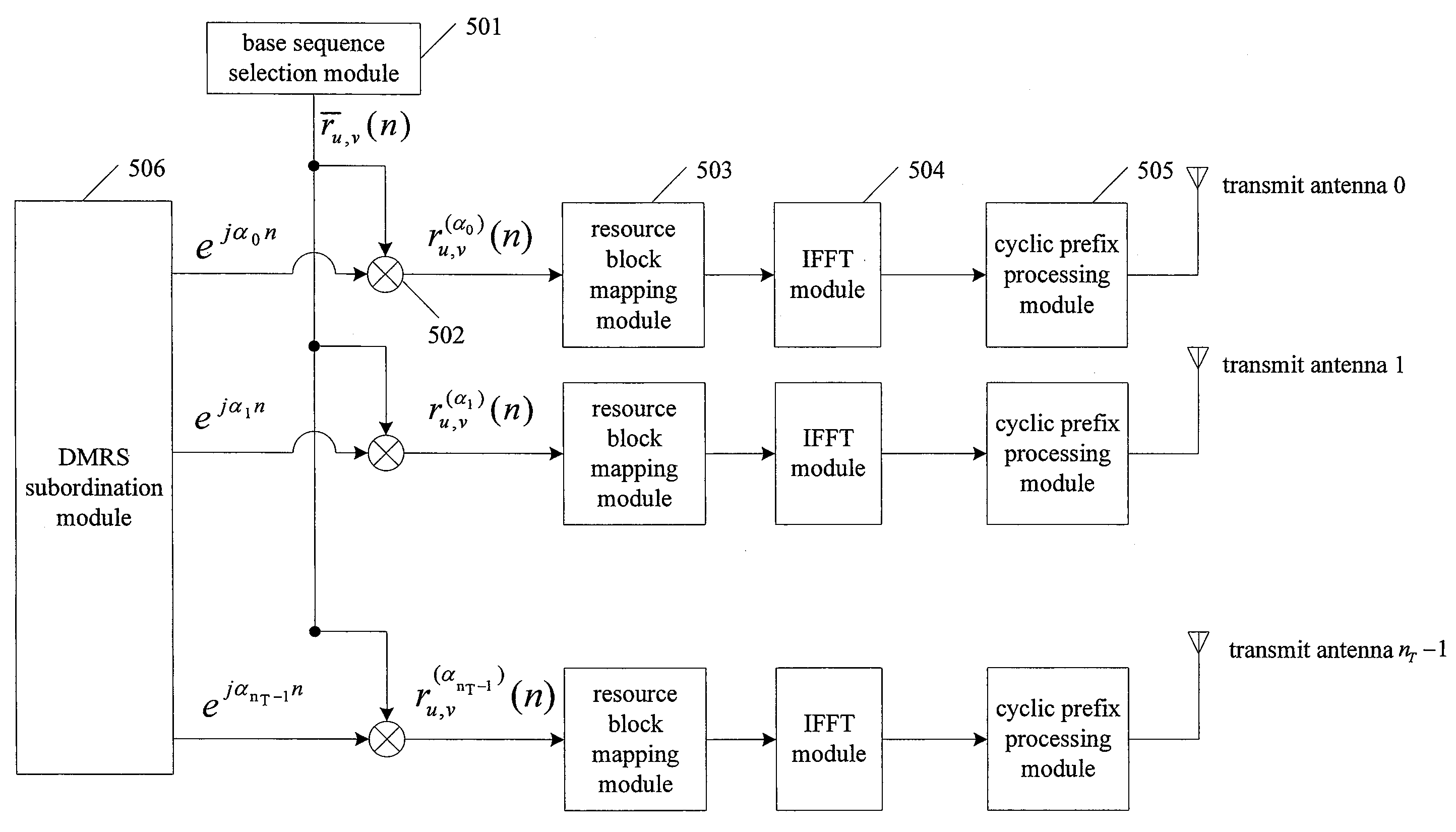
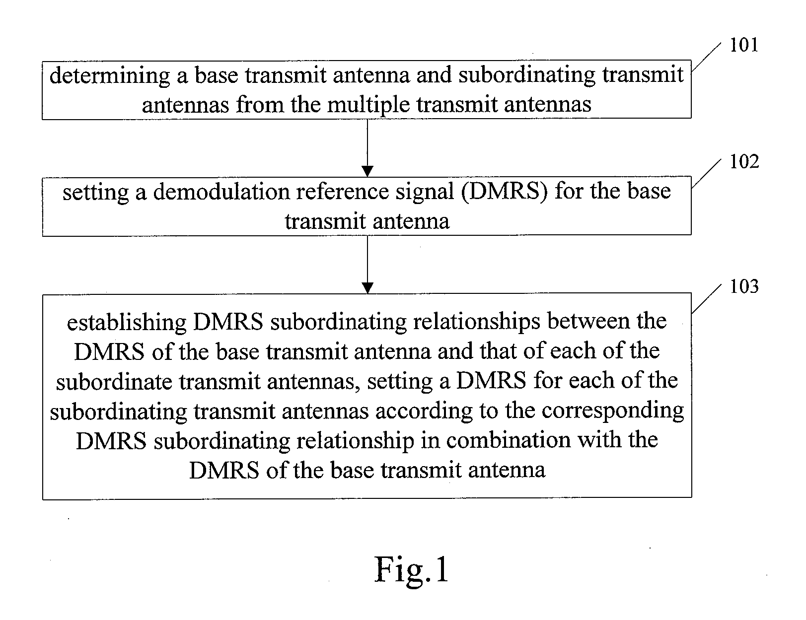
[0068]In accordance with an embodiment of the present invention, the uplink system has multiple transmit antennas. It is assumed that the number of the transmit antennas nT≧2, that is, the uplink system includes transmit antennas 0, 1, . . . , nT−1. As shown in FIG. 1, a method for providing demodulation reference signals in the uplink system includes the following steps:

[0069]Step 101: determining a base transmit antenna and subordinating transmit antennas from the multiple transmit antennas.

[0070]In detail, one transmit antenna is selected as the base transmit antenna from the nT transmit antennas, and other nT−1 transmit antennas are all subordinating transmit antennas. For example, transmit antenna 0 can be selected as the base transmit antenna, and thus transmit antennas 1, . . . , nT−1 ar...


PUM


Abstract

The present invention discloses a method for determining an uplink demodulation reference signal (DMRS), which includes: taking one of multiple transmit antennas in the uplink as a base transmit antenna, taking other transmit antennas as subordinating transmit antennas and setting a DMRS for the base transmit antenna; establishing DMRS subordinating relationships between the base transmit antenna and each of the subordinating transmit antennas; and setting a DMRS for each of the subordinating transmit antennas according to the DMRS of the base transmit antenna and the DMRS subordinating relationship between the base transmit antenna and each of the subordinating transmit antennas. The present invention also provides a user equipment (UE) and an uplink system for providing DMRSs for multiple transmit antennas. The method, UE and system are applicable in both SU-MIMO transmission and MU-MIMO transmission.

Description

FIELD OF THE INVENTION[0001]The present invention relates to wireless communications technologies, and especially to a method for determining demodulation reference signals in the uplink, a user equipment (UE) and an uplink system of the wireless communications system.BACKGROUND OF THE INVENTION[0002]3GPP Long Term Evolution (LTE) project is an evolution and innovation for current 3G technologies, which can substantially increase spectral efficiency and cell capacity, and also can flexibly support multiple kinds of bandwidth configuration. The uplink of the LTE system adopts a single carrier frequency division multiple access (SC-FDMA) technology, which has low Peak-to-Average Power Ratio (PAPR) and can support a wide range of coverage effectively. Taking into consideration the constraint of the cost and the standardization progress of a UE, the existing uplink of the LTE system adopts a single-antenna rather than a multi-antenna technology to transmit signals of a UE. It should be ...

Claims


Application Information

Patent Timeline
Patent Type & Authority Applications(United States)
IPC IPC(8): H04B7/02H04J11/00H04J99/00H04L27/01H04W28/18
CPCH04B7/0413H04L27/2607H04B7/0691H04B7/0667
Inventor HOU, XIAOLINZHANG, ZHANKAYAMA, HIDETOSHI
Owner NTT DOCOMO INC
Why Eureka
Try Eureka