Dc/ac power inverter control unit of a resonant power converter circuit, in particular a dc/dc converter for use in a high-voltage generator circuitry of a modern computed tomography device or x-ray radiographic system

a power inverter and control unit technology, applied in the direction of electric variable regulation, process and machine control, instruments, etc., can solve the problems of unwanted losses, asymmetric current distribution, unwanted losses, etc., and achieve the effect of zero current operation

Inactive Publication Date: 2011-01-06
KONINKLIJKE PHILIPS ELECTRONICS NV
View PDF4 Cites 40 Cited by
  • Summary
  • Abstract
  • Description
  • Claims
  • Application Information

AI Technical Summary

Benefits of technology

[0015]According to the present invention, said X-ray radiographic imaging system, 3D rotational angiography device or X-ray computed tomography device may comprise a DC/AC power inverter control unit which may be adapted to minimize the magnitude of the inverter output current

Problems solved by technology

As a consequence, zero current switching is no longer ensured for all operation points, which leads to an introduction of unwanted losses.
If the DC/AC power inverter stages are operated togethe

Method used


Image

  • Dc/ac power inverter control unit of a resonant power converter circuit, in particular a dc/dc converter for use in a high-voltage generator circuitry of a modern computed tomography device or x-ray radiographic system
  • Dc/ac power inverter control unit of a resonant power converter circuit, in particular a dc/dc converter for use in a high-voltage generator circuitry of a modern computed tomography device or x-ray radiographic system
  • Dc/ac power inverter control unit of a resonant power converter circuit, in particular a dc/dc converter for use in a high-voltage generator circuitry of a modern computed tomography device or x-ray radiographic system

Examples


Embodiment Construction

[0029]In the following sections, an exemplary embodiment of the claimed DC / DC power converter circuit as well as an exemplary embodiment of the claimed control method according to the present invention will be explained in more detail, thereby referring to the accompanying drawings.

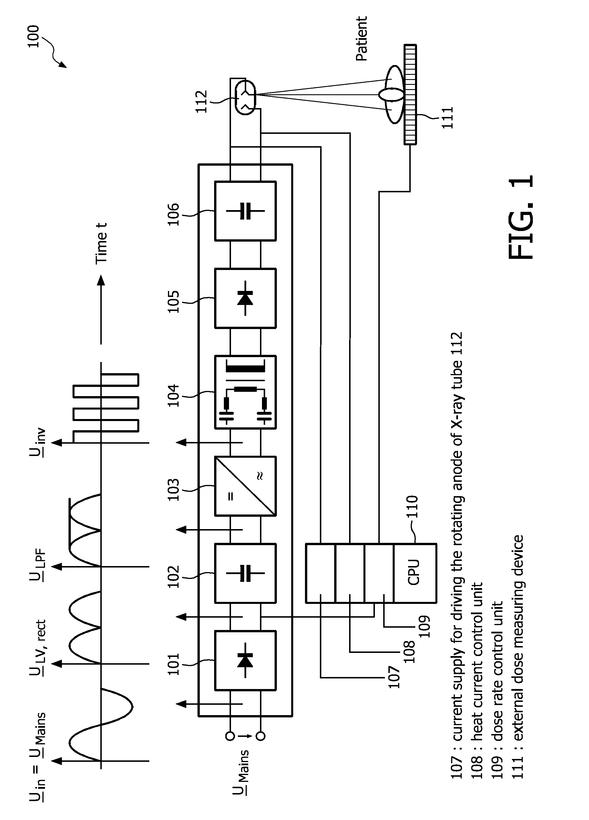
[0030]FIG. 1 illustrates the principle of high-frequency inverter technology, which is also known as direct voltage conversion. It thereby shows the principle components of a conventional multi-pulse high-voltage generator used for providing the supply voltage of an X-ray tube 112. First, an intermediate DC voltage ULPF with more or less ripple is generated by rectifying and low-pass filtering an AC voltage UMains which is supplied by the mains, thereby using an AC / DC converter stage 101 followed by a first low-pass filtering stage 102, wherein the latter may simply be realized by a single smoothing capacitor. Although the electric output power will naturally differ, the same high-voltage quality can be o...


PUM


Abstract

The present invention refers to a DC/AC power inverter control unit of a resonant-type power converter circuit (400), in particular a DC/DC converter, for supplying an output power for use in, for example, a high-voltage generator circuitry of an X-ray radio-graphic imaging system, 3D rotational angiography device or X-ray computed tomography device of the fan-or cone-beam type. More particularly, the present invention is directed to a resonant-type power converter circuit out which comprises an interphase transformer (406) connected in series to at least one series resonant tank circuit (403a and 403a′ or 403b and 403b′) at the output of two DC/AC power inverter stages (402a+b) supplying a multi-primary winding high-voltage transformer (404), wherein said interphase transformer (406) serves for removing the difference (DI) in the resonant output currents (1 and 2) of the DC/AC power inverter stages (402a+b). Furthermore, the present invention is dedicated to a control method which assures that the interphase transformer (406) is not saturated. This control method ensures zero current operation and provides for that input power losses can be minimized.

Description

[0001]The present invention refers to a DC / AC power inverter control unit of a resonant-type power converter circuit, in particular a DC / DC converter, for supplying an output power for use in, for example, a high-voltage generator circuitry of an X-ray radiographic imaging system, 3D rotational angiography device or X-ray computed tomography device of the fan- or cone-beam type. More particularly, the present invention is directed to a resonant-type power converter circuit which comprises an interphase transformer connected in series to at least one series resonant tank circuit at the output of two DC / AC power inverter stages supplying a multi-primary winding high-voltage transformer, wherein said interphase transformer serves for removing the difference in the resonant output currents of the DC / AC power inverter stages. Furthermore, the present invention is dedicated to a control method which assures that the interphase transformer is not saturated. This control method ensures zero...

Claims


Application Information

Patent Timeline
IPC IPC(8): H02M7/5387H02M3/335H05G1/10
CPCH02M1/40Y02B70/1441H02M7/53873Y02B70/10H02M1/0064
Inventor HATTRUP, CHRISTIANSCHEEL, THOMASLUERKENS, PETER
Owner KONINKLIJKE PHILIPS ELECTRONICS NV
Why Eureka
Try Eureka