

Plasma CVD apparatus, plasma CVD method, and agitating device
Inactive Publication Date: 2011-01-06
ADVANCED MATERIAL TECH INC
View PDF13 Cites 16 Cited by
- Summary
- Abstract
- Description
- Claims
- Application Information
AI Technical Summary
Benefits of technology
[0007]Incidentally, the above-described conventional plasma CVD apparatus can not generate plasma intensively near fine particles 1 housed in the container 129, but plasmas are generated in regions separated from fine particles 1 in the container and plasmas spread wholly and disperse. Consequently, there is such a problem that the amount of applied electric power becomes large relative to the amount of coated fine particles to be obtained to thereby lower the energy efficiency.
Problems solved by technology
Consequently, there is such a problem that the amount of applied electric power becomes large relative to the amount of coated fine particles to be obtained to thereby lower the energy efficiency.
Moreover, since fine particles having small diameters have such properties that they agglutinate, it was not easy to sufficiently stir such fine particles.
Method used
View moreImage
Smart ImageViewing Examples

Examples
example
Condition of Film Formation
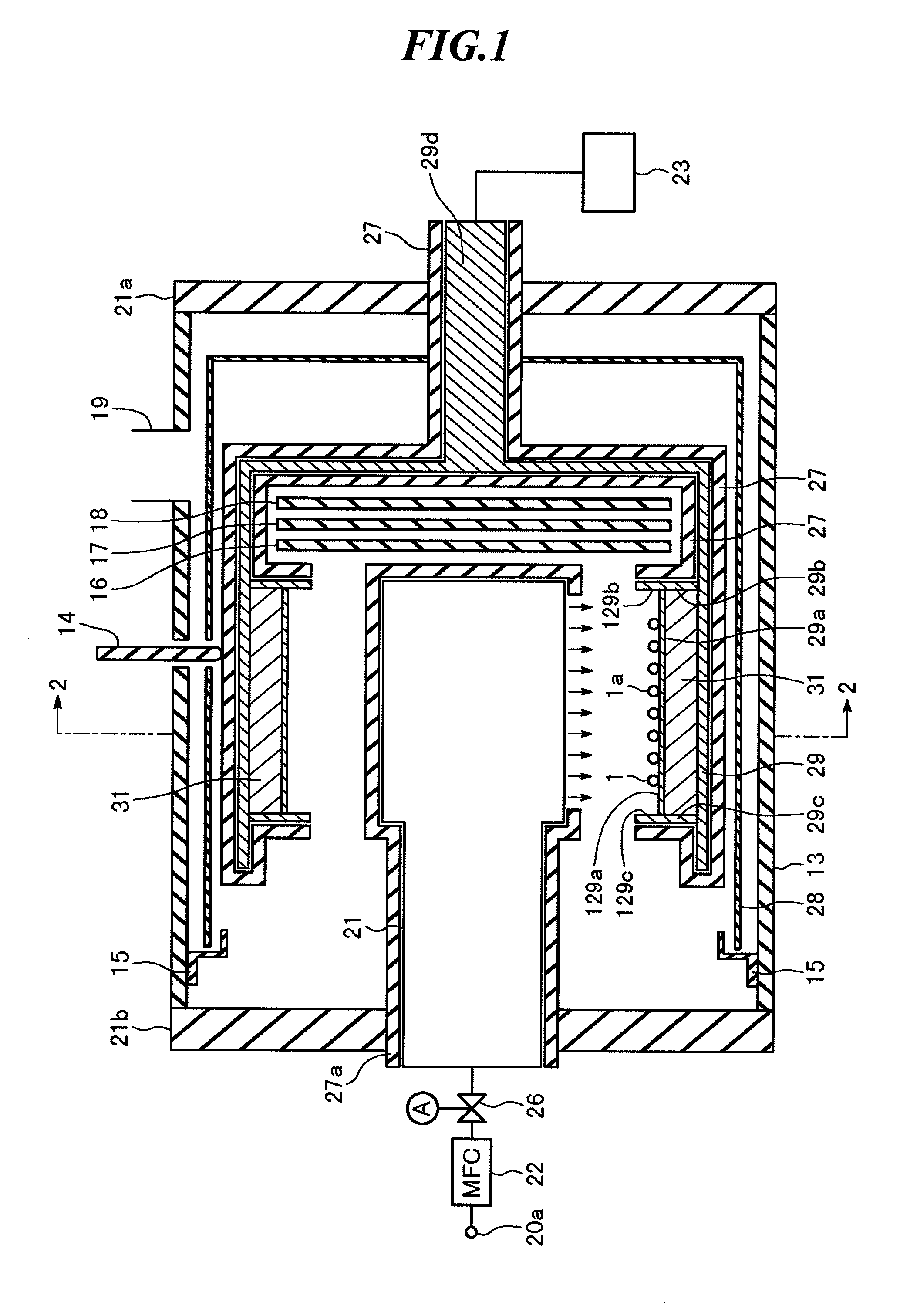
[0212]Plasma CVD apparatus in FIG. 1
Frequency of RF power source: 250 kHz
Glass sample: 25×75×1 mm
Flow rate of C7H8: 7 cc / min
Flow rate of Ar: 3 cc / min
Reaction pressure: 9.5 Pa
RF output: 150 W
Film time (no rotation): 30 min
(Result of Film Formation)
[0213]Film thickness: 1.153 μm
Knoop hardness (5 g): 2072
[0214]In the Example, a very hard DLC film was formed. Such hard DLC film is excellent in abrasion resistance.
Login to View More PUM
| Property | Measurement | Unit |
|---|---|---|
| Length | aaaaa | aaaaa |
| Diameter | aaaaa | aaaaa |
| Frequency | aaaaa | aaaaa |
Abstract
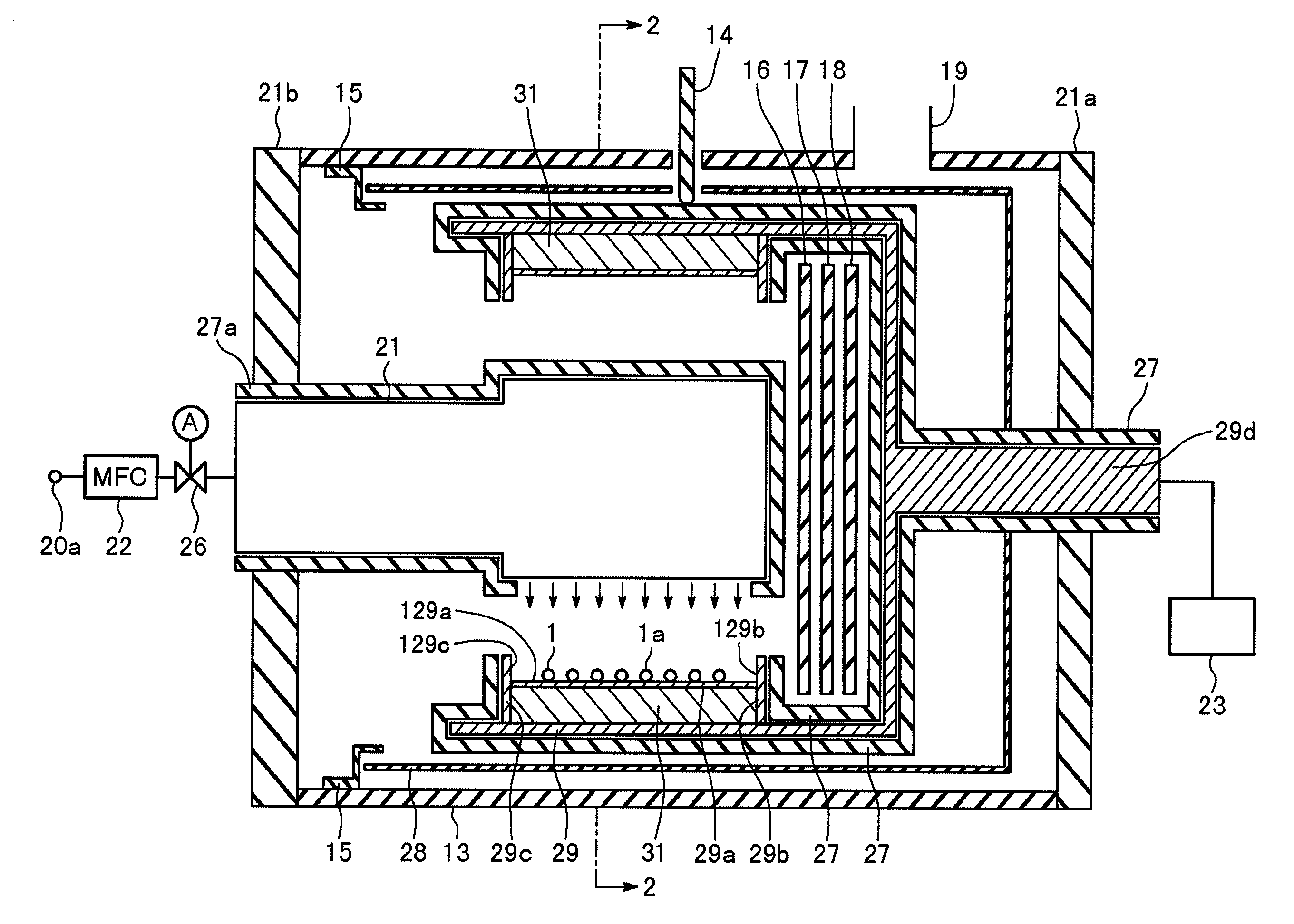
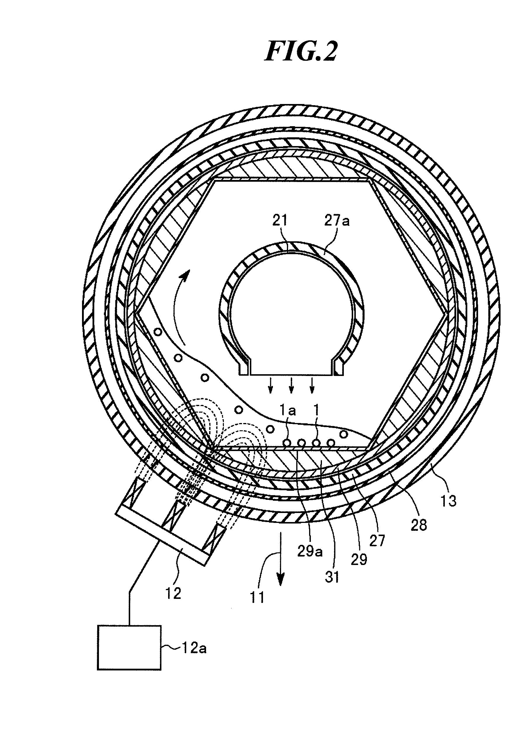
The present invention provides a plasma CVD apparatus and a plasma CVD method capable of efficiently coating the surfaces of fine particles with a thin film or super-fine particles by concentrating a plasma near the fine particles. The plasma CVD apparatus according to the present invention is characterized by including a chamber 13, a container disposed in the chamber for housing fine particles 1, the container having a polygonal inner shape in a section approximately parallel to the direction of the gravity,a ground shielding member 27 for shielding the surface of the container other than a housing face for housing the fine particles 1, a rotation mechanism for causing the container to rotate or act as a pendulum on the axis of rotation approximately perpendicular to the section,an opposed electrode 21 disposed in the container so as to face the housing face,a plasma power source 23 electrically connected to the container,a gas introducing mechanism for introducing a raw gas into the container, andan evacuation mechanism for evacuating the inside of the chamber.
Description
TECHNICAL FIELD[0001]The present invention relates to a plasma CVD (Chemical Vapor Deposition) apparatus and a plasma CVD method capable of coating the surfaces of fine particles or electronic parts efficiently with a thin film or super-fine particles by concentrating a plasma near the fine particles. Moreover, the present invention relates to an agitating device for agitating fine particles or electronic parts having small diameters.BACKGROUND ART[0002]FIG. 9 (A) is a cross-sectional view showing the outline of a conventional plasma CVD apparatus, and FIG. 9 (B) is a cross-sectional view along the 7B-7B line shown in FIG. 9 (A).[0003]The plasma CVD apparatus has a cylindrical chamber 3. The both ends of the chamber 3 are closed with chamber covers 20. Inside the chamber 3, a container 129 is disposed. A section of the container 129 is cylindrical as shown in FIG. 9 (B). And, the container 129 is constituted so as to house granular materials (fine particles) 1 being an object to be ...
Claims
Login to View More Application Information
Patent Timeline
 IPC IPC(8): C23C16/458C23C16/00C23C16/50
CPCB01J2/006B01J2/12C23C16/26C23C16/4417H01J2237/20214H01J37/32568H01J37/32633H01J37/3266H01J2237/20207C23C16/442
InventorHONDA, YUUJIABE, TAKAYUKI
OwnerADVANCED MATERIAL TECH INC