Method of producing difluoromethane

a technology of difluoromethane and difluoromethane, which is applied in the field of producing difluoromethane, can solve the problems of low energy efficiency and productivity reduction, and achieve the effect of high yield

Inactive Publication Date: 2005-01-11
FOOSUNG
View PDF3 Cites 12 Cited by
  • Summary
  • Abstract
  • Description
  • Claims
  • Application Information

AI Technical Summary

Benefits of technology

Therefore, it is an object of the present invention is to provide a method of producing HFC-32 in high yield under mild reaction conditions in which a relatively small quantity of energy is consumed.
The present inventors have conducted extensive studies into the method of producing HFC-32, keeping in mind a fact that a conventional gas phase method has disadvantages of large energy consumption due to a high reaction temperature and generation of great quantities of side products causing productivity to be reduced, and a conventional liquid phase method has disadvantages of severe corrosion of the reactor and low energy efficiency, resulting in the finding that HFC-32 is produced in high yield under mild reaction conditions using a relatively small amount of energy by catalytically reacting HCC-30 with HF in gas phase at a relatively low temperature of 340° C. or lower to produce chlorofluro methane (CH2FCl, hereinafter referred to as “HCFC-31”), and catalytically reacting chlorofluro methane with HF in liquid phase at 60 to 100° C., thereby accomplishing the present invention. At this time, energy efficiency is improved because heat generated during a gas phase reaction is utilized in a liquid phase reaction.

Problems solved by technology

The present inventors have conducted extensive studies into the method of producing HFC-32, keeping in mind a fact that a conventional gas phase method has disadvantages of large energy consumption due to a high reaction temperature and generation of great quantities of side products causing productivity to be reduced, and a conventional liquid phase method has disadvantages of severe corrosion of the reactor and low energy efficiency, resulting in the finding that HFC-32 is produced in high yield under mild reaction conditions using a relatively small amount of energy by catalytically reacting HCC-30 with HF in gas phase at a relatively low temperature of 340° C. or lower to produce chlorofluro methane (CH2FCl, hereinafter referred to as “HCFC-31”), and catalytically reacting chlorofluro methane with HF in liquid phase at 60 to 100° C., thereby accomplishing the present invention.

Method used


Image

  • Method of producing difluoromethane

Examples


example

Gas Phase Reaction

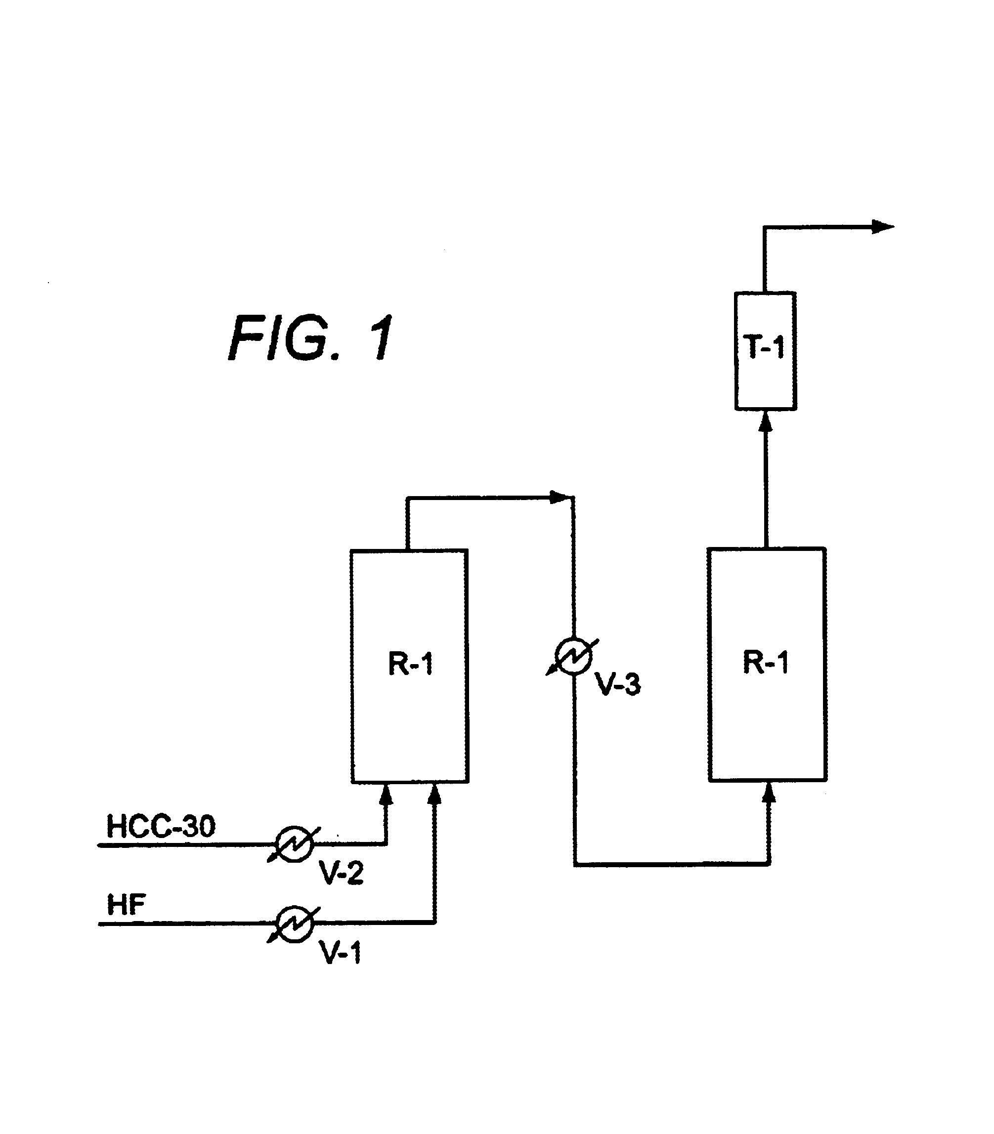
1.2 kg of alumina catalyst in which 8 wt % chromium oxide was supported by alumina was stuffed in an Inconel pipe with volume of 3 L, thereby accomplishing a first reactor R-1. Vaporized hydrogen fluoride and nitrogen gas were fed into the first reactor R-1 heated to 300° C. to fluorinate the catalyst. HCC-30 and hydrogen fluoride were then fed into the first reactor. At this time, 2 to 10 moles hydrogen fluoride per unit mole HCC-30 was fed into the first reactor under 8 to 12 kg / cm2G for 15 to 20 sec. Products obtained from the first reactor were heat-exchanged and then used as raw material of a liquid phase reaction.

Liquid Phase Reaction

A SbCl5 catalyst was stuffed into a 16 L second reactor lined with PTFE, resin, hydrogen fluoride was fed into the second reactor at 50° C. to fluorinate the SbCl5 catalyst, and hydrogen fluoride (HF) was fed into the second reactor in such a way that a liquid level in the second reactor was maintained at 50%. Products obtained f...


PUM

PropertyMeasurementUnit
temperatureaaaaaaaaaa

Abstract

A method of producing difluoromethane (HFC-32), which includes firstly reacting methylene chloride with hydrogen fluoride in gas phase at 280 to 340° C. in the presence of a fluorination catalyst to produce chlorofluoro methane, and secondly reacting the chlorofluoro methane with hydrogen fluoride in liquid phase at 60 to 80° C. in the presence of an antimony chloride catalyst. The method is advantageous in that HFC-32 is produced in high yield under mild reaction conditions using a relatively small amount of energy.

Description

RELATED U.S. APPLICATIONSNot applicable.STATEMENT REGARDING FEDERALLY SPONSORED RESEARCH OR DEVELOPMENTNot applicable.REFERENCE TO MICROFICHE APPENDIXNot applicable.FIELD OF THE INVENTIONThe present invention pertains to a method of producing difluoromethane.BACKGROUND OF THE INVENTIONAs well known to those skilled in the art, chlorofluorocarbon-based compounds conventionally used as foaming agents, abluents, aerosol propellants, and coolants, are known as materials with high ozone-depleting potential which destroy the ozone layer in the stratosphere, and so have been replaced with hydrochlorofluorocarbon (hereinafter, referred to sometimes as “HCFC”). However, recently, HCFC based materials are prone to be replaced with hydrofluorocarbon (hereinafter, referred to sometimes as “HFC”) compounds, without ozone-depleting potential, because HCFC-based materials still have ozone depleting potential, even though its value is low.Difluoromethane (CH2F2, hereinafter referred to sometimes as...

Claims


Application Information

Patent Timeline
Patent Type & Authority Patents(United States)
IPC IPC(8): C07C19/00C07C17/00C07C19/08C07C17/20
CPCC07C17/206C07C19/08C07C19/10C07C17/20
Inventor YUICHI, IIKUBOJI, HAE SEOKCHO, OOK JAE
Owner FOOSUNG
Why Eureka
Try Eureka