Filter fan

a filter fan and fan body technology, applied in the field of filter fans, can solve the problems of low dust capacity, low production efficiency, and high pressure drop, and achieve the effects of low production cost, low differential pressure, and low necessary blast power

Active Publication Date: 2011-01-13
PFANNENBERG GMBH
View PDF34 Cites 9 Cited by
  • Summary
  • Abstract
  • Description
  • Claims
  • Application Information

AI Technical Summary

Benefits of technology

[0006]The object of the invention is to improve a filter fan in such a manner that it can be produced as economically as possible, that it makes possible an air throughput as high as possible for a low necessary blast power and a low differential pressure and that it guarantees a protection against moisture as high as possible and a high dust capacity.

Problems solved by technology

Moreover, the blasts have usually comparably low performances so that the pressure drop at the filter insert is to be held as low as possible in order not to reduce unadmittedly the cooling power due to the filter agent itself.
However, such filter membranes have the disadvantage that they cause a comparably high pressure drop and have in particular a low dust capacity.
Moreover, the corresponding filter membranes are laminated which has a disadvantageous economic influence on the fabrication of the filters.
In particular, when certain properties are provided for, which either the carrier material or the membrane itself does not have, the respective material must be equipped correspondingly, whereby the equipment eventually of two components of the laminate before the laminating procedure is complicated and eventually makes the laminating procedure more difficult and can thus again have a disadvantageous economical influence.

Method used


Image

  • Filter fan
  • Filter fan
  • Filter fan

Examples


Embodiment Construction

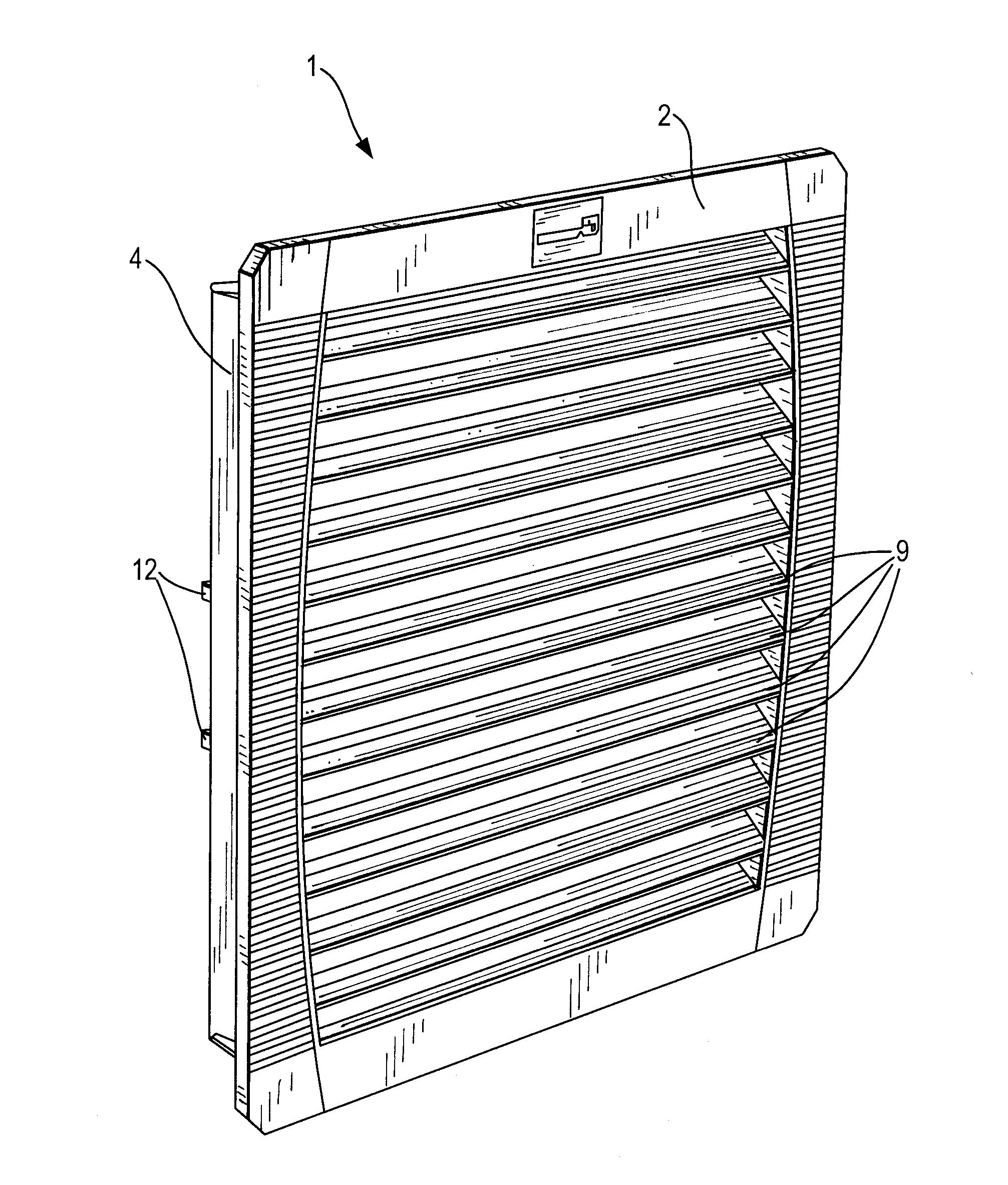
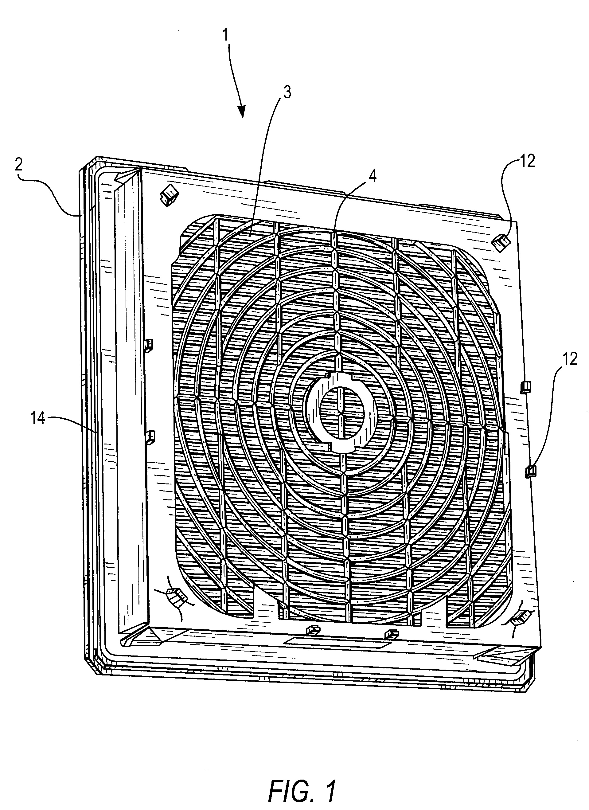
[0030]In FIG. 1, a protective cover of a filter fan is designated on the whole by 1. The protective cover 1 has an outer covering grid 2, turned off the observer of FIG. 1, whereby only the rear side of a peripheral frame can be seen. Furthermore, the protective cover 1 has a filter element 3 which is configured as a folded filter and is covered by a rear protective grid 4 which is on the clean side of the filter element 3. The blast of the filter fan is provided behind the protective grid in flow direction of the air, thus on the side of the protective cover 1 which is turned to the observer in FIG. 1.

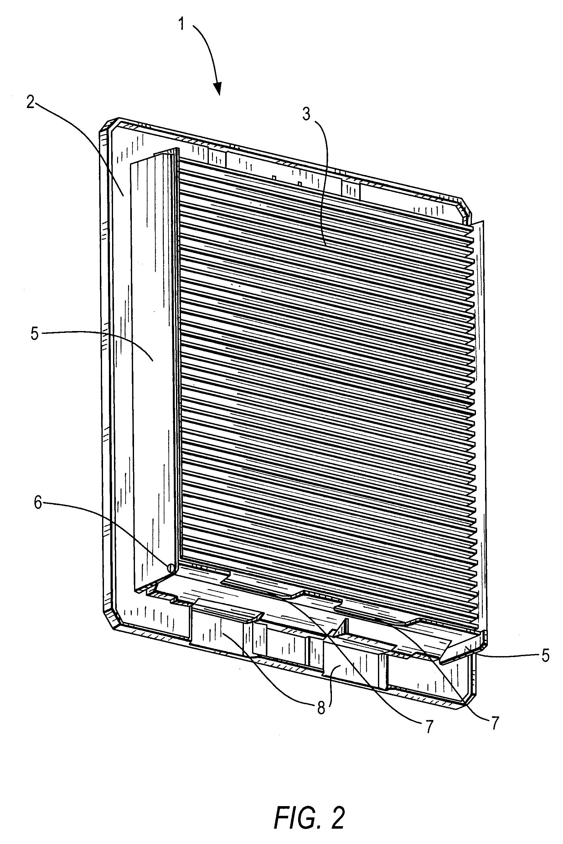
[0031]FIG. 2 shows the protective cover 1 with removed protective grid. The single folds of the filter element 3 can clearly be seen and two side walls 5 can be recognized which are moulded on the rear side of the covering grid 2 and between which the filter element 3 is. Webs which cause a press fit of the filter element 3 extend to the filter element 3 on the side walls 5 so that th...


PUM

PropertyMeasurementUnit
mean pore sizeaaaaaaaaaa
distanceaaaaaaaaaa

Abstract

A filter fan of a switch cupboard or of an electrical and/or electronic device placed in a casing with a blast producing an air flow and with a filter element (3) which is placed in the air flow and separates a clean side, on which the blast is placed, from an unclean side, wherein the filter element is held in a frame which can be fixed on the casing by covering the air passage opening penetrating through the casing wall and wherein a protective grid (4) is placed between the filter element (3) and the blast, the invention proposes that a bridging-free distance is provided between the filter surface of the filter element (3) and the protective grid (4), wherein this distance is dimensioned so as to make possible the discharge of water drops on the clean side surface of the filter element and to avoid a contact of the water drops with the protective grid.

Description

BACKGROUND OF THE INVENTION[0001]1. Field of the Invention[0002]The present invention relates to a filter fan.[0003]2. Description of the Related Art[0004]Filter fans are known is practice. The filter means, in particular a nonwoven mat, is held in a frame which is closed to the outside by a covering grid and to the blast by a protective grid, whereby the nonwoven mat is held between both grids and adheres to both grids. The filter fans are used for example in switch cupboards and in other casings, namely in a cut-out of the respective casing wall in order to cool electrical or electronic components placed in the casing. This being, it is provided to keep the dust charge as low as possible in order not to reduce unintentionally the cooling power by a dust layer which is depositing on the electrical components. Moreover, the blasts have usually comparably low performances so that the pressure drop at the filter insert is to be held as low as possible in order not to reduce unadmitted...

Claims


Application Information

Patent Timeline
Patent Type & Authority Applications(United States)
IPC IPC(8): B01D50/00
CPCB01D45/08B01D46/0031B01D46/10H05K7/20181B01D2279/45F04D29/703B01D50/002B01D50/20
Inventor PFANNENBERG, ANDREAS
Owner PFANNENBERG GMBH
Why Eureka
Try Eureka