Thermal module and manufacturing method thereof

a technology of thermal modules and manufacturing methods, applied in indirect heat exchangers, lighting and heating apparatuses, laminated elements, etc., can solve the problems of time-consuming and complex, and the heat dissipation capability of thermal modules is thus greatly reduced

Inactive Publication Date: 2011-01-13
FU ZHUN PRECISION IND SHENZHEN +1
View PDF5 Cites 19 Cited by
  • Summary
  • Abstract
  • Description
  • Claims
  • Application Information

AI Technical Summary

Problems solved by technology

In manufacturing the thermal module, the substrate is defined with the recesses, and the heat pipes are assembled to the recesses of the substrate, which is time-consuming and complex.
Furthermore, due to a technical restriction, ...

Method used


Image

  • Thermal module and manufacturing method thereof
  • Thermal module and manufacturing method thereof
  • Thermal module and manufacturing method thereof

Examples


third embodiment

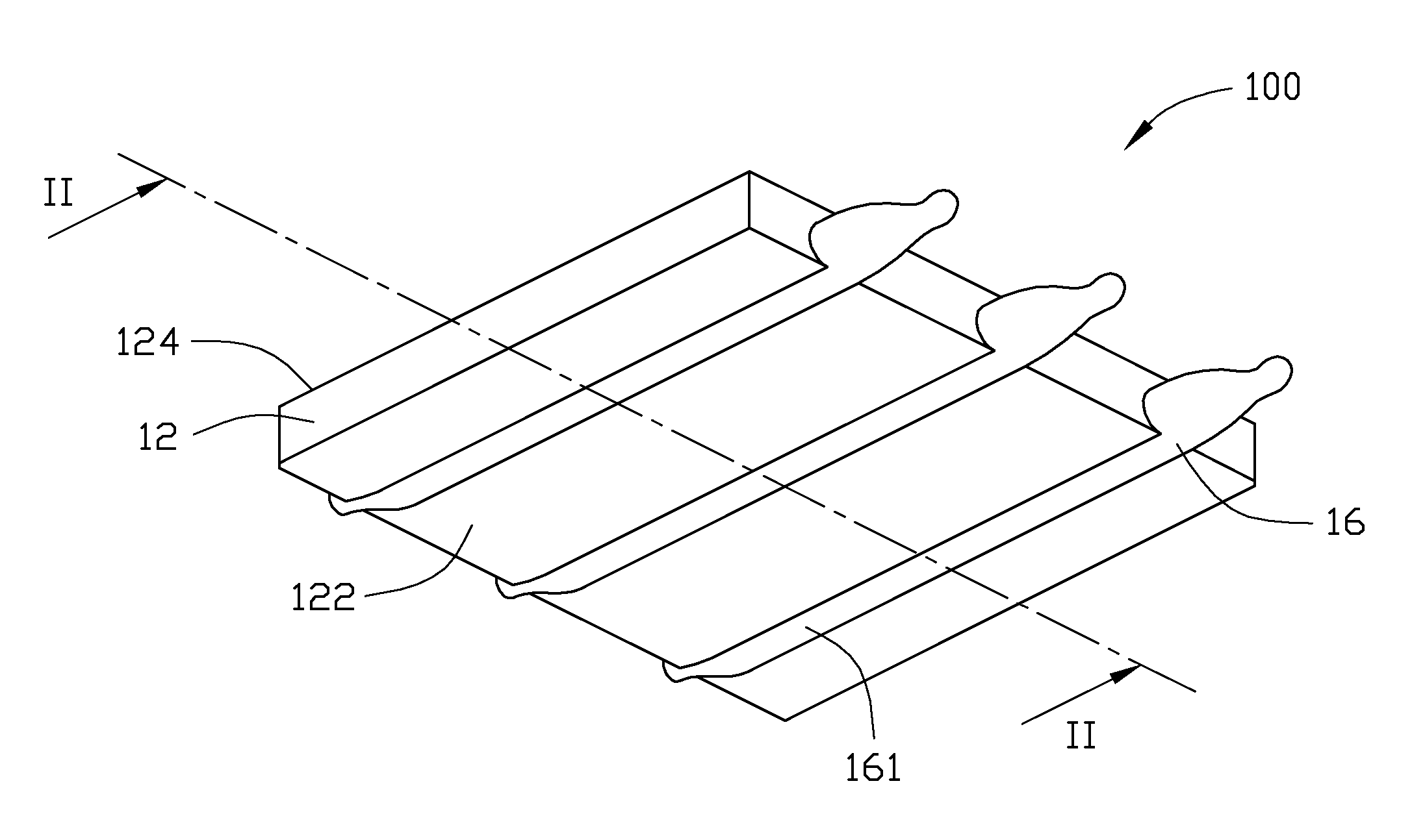
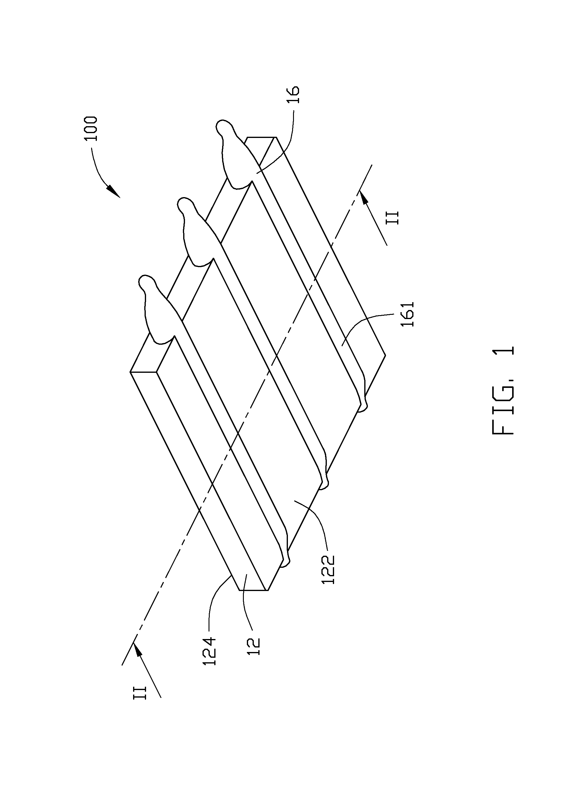
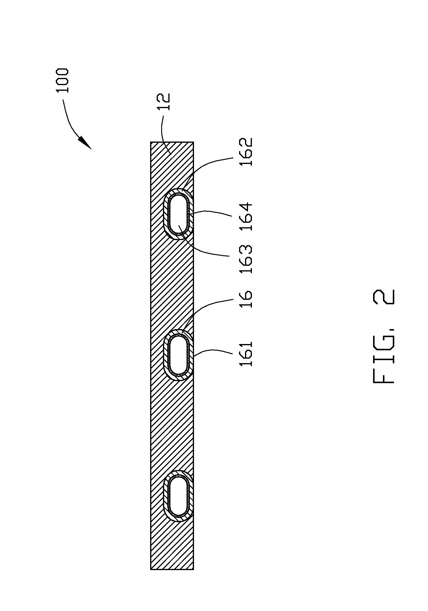
[0021]FIG. 6 shows a thermal module 300 according to a The thermal module is similar to the previous first thermal module 100. The thermal module 300 includes a substrate 32 and a plurality of heat pipes 36. The substrate 32 forms a bottom surface 322 and a top surface 324 opposite to the bottom surface 322. The thermal module 300 differs from the first thermal module 100 in that a plurality of fins 34 are integrally formed on the top surface 324 of the substrate 32, and a shape of the heat pipes 36 is different from the heat pipes 16 of the first thermal module 100. The heat pipes 36 of the thermal module 300 each are U-shaped, including an evaporating section 362 and a condensing section 362 parallel to the evaporating section 362. The evaporating section 362 is integrally embedded in the substrate 32, while the condensing section 364 extends through and thermally connects with the fins 34. The evaporating section 362 of each of the heat pipes 36 forms a planar contacting surface...

first embodiment

[0022]A method of manufacturing the thermal module 300 is similar to the method of manufacturing the previous thermal module 100 of the When the thermal module 300 is manufactured, a plurality of tubes each with a wick structure attached to an inner surface thereof are firstly provided. Each of the tubes is flat in cross section and U-shaped in profile. Each tube includes a first section used for forming the evaporating section 362 of the heat pipe 36 and a second section used for forming the condensing section 364 of the heat pipe 36. One end of each of the tubes is open and the other end of each of the tubes is sealed. Secondly, the tubes are placed into a mold which is applied for forming the substrate 32 and the fins 34. Thirdly, a molten metal is injected into the mold to simultaneously form the substrate 32 and the fins 34 wherein the first sections of the tubes are integrally embedded in the substrate 32 and the second sections of the tubes integrally extend through the fins...


PUM


Abstract

A thermal module includes a substrate and a heat pipe integrally embedded in the substrate by insert molding technique. An end of the heat pipe protrudes laterally out of the substrate. The heat pipe includes a tube, a wick structure attached to an inner surface of the tube and a working fluid filled in the tube. A method for manufacturing the thermal module includes following steps: providing a tube with a wick structure attached to an inner surface thereof, an end of the tube being open; placing the tube into a mold; injecting a molten metal into the mold to form a substrate with the tube being integrally embedded in the substrate and the open end of the tube protruding laterally out of the substrate; filling a working fluid into the tube via the open end; sealing the open end of the tube.

Description

BACKGROUND[0001]1. Technical Field[0002]The present disclosure relates to a thermal module and a manufacturing method of the thermal module.[0003]2. Description of Related Art[0004]With continuing development of electronic technology, heat-generating electronic components such as CPUs (central processing units) are generating more and more heat which requires immediate dissipation. Generally, thermal modules are attached to the electronic components to provide such dissipation.[0005]A conventional thermal module includes a substrate, a fin assembly and a plurality of heat pipes connecting the fin assembly with the substrate. The substrate defines a plurality of elongated recesses for receiving the evaporator sections of the heat pipes. The evaporator sections of the heat pipes are respectively received in the recesses of the substrate and fixed to the substrate by soldering. Usually, a thermal interface material such as thermal grease is applied in the recesses to reduce air gaps be...

Claims


Application Information

Patent Timeline
IPC IPC(8): F28D15/04F28F7/00B21D53/02
CPCF28D15/0233F28D15/0266F28D15/0275F28D15/046F28F3/02Y10T29/4935H05K7/20336H01L2924/0002H01L23/427Y10T29/49353H01L2924/00
Inventor YU, YE-FEIZHA, XIN-XIANGJIN, XIAN-MINKUO, JER-HAUR
Owner FU ZHUN PRECISION IND SHENZHEN
Why Eureka
Try Eureka