Eureka AIR delivers breakthrough ideas for toughest innovation challenges, trusted by R&D personnel around the world.

Horizontal directional drilling system

Inactive Publication Date: 2011-01-13
CHARLES MACHINE WORKS
View PDF7 Cites 17 Cited by
  • Summary
  • Abstract
  • Description
  • Claims
  • Application Information

AI Technical Summary

Benefits of technology

[0007]Thanks to the invention there is provided a horizontal directional drilling system that is surprisingly fast, easy to operate, relatively inexpensive and which at the same time provides the synergetic effect of consuming a relatively low amount of energy.

Problems solved by technology

They are advantageous in many aspects but restricted to a limited range of operations, e.g. due to not being steerable.
This invention provides steerable control in horizontal directional drilling operations, but presents numerous disadvantages, e.g. complex and costly interconnections.
Use of hydraulic pump or a cam assembly to operate the hammer does not provide optimization of the process of making a borehole.
Thus, horizontal directional drilling systems utilizing hydraulic pumps or cam assembly to operate the drilling are characterized by relatively high cost and relatively low productivity as the system is slow.

Method used


Image

  • Horizontal directional drilling system
  • Horizontal directional drilling system
  • Horizontal directional drilling system

Examples


Embodiment Construction

[0016]Various embodiments are described with reference to the drawings, wherein like reference numerals are used to refer to like elements throughout. In the following description, for purposes of explanation, numerous specific details are set forth in order to provide a thorough understanding of one or more embodiments. It may be evident, however, that such embodiments may be practiced without these specific details.

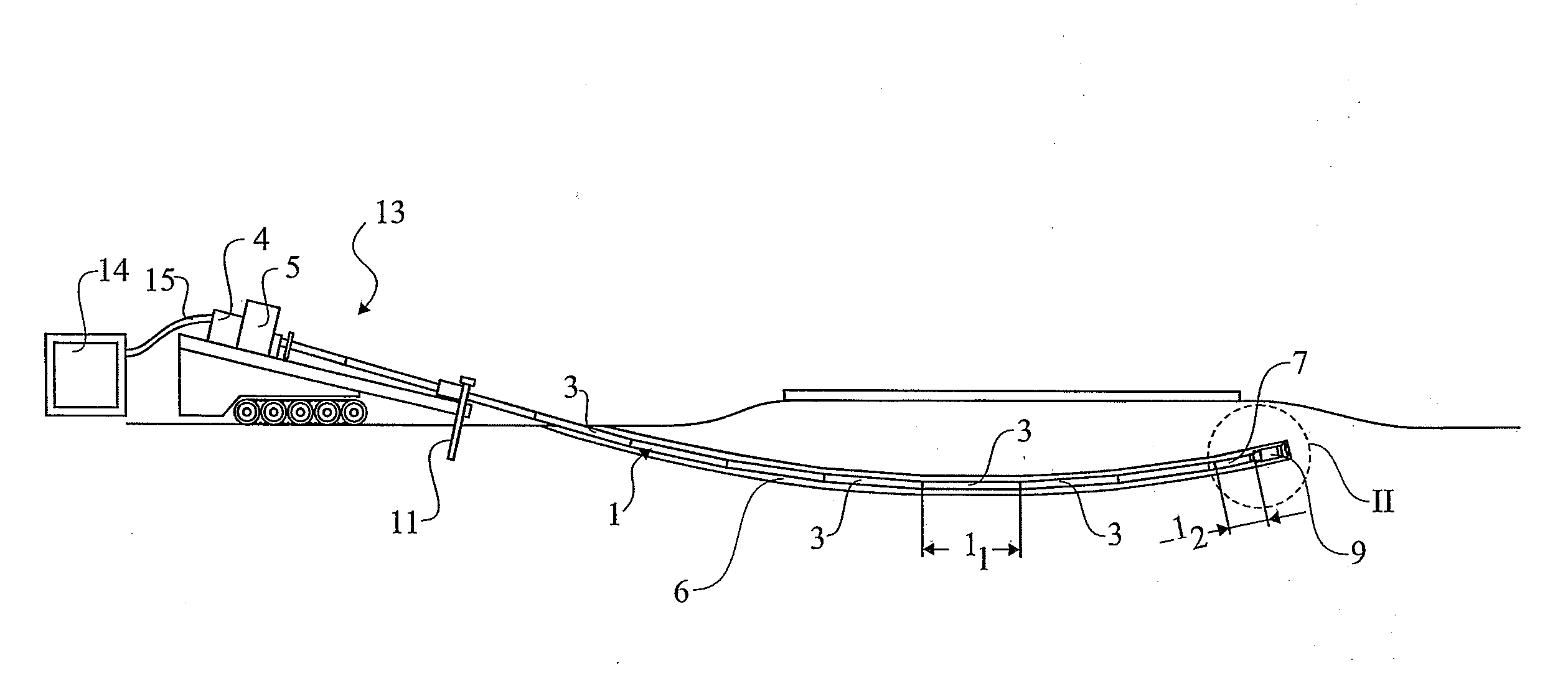
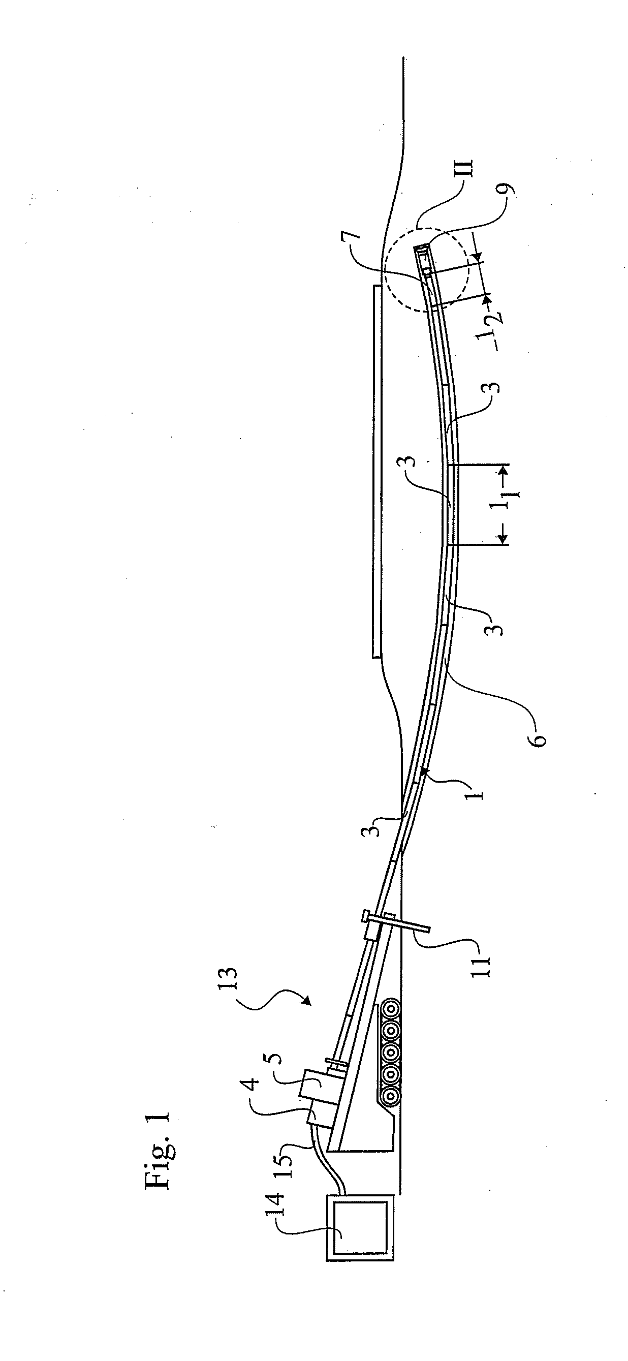
[0017]FIG. 1 illustrates a horizontal directional drilling system in accordance with an embodiment of the invention. The horizontal directional drilling system may be used to make a borehole 6, without disturbing an above ground structure. The horizontal directional drilling system comprises rotary drive systems 4, 5 on a moveable base 13, an earth anchor 11, a dual string 1 and equipment 14, 15 to supply pressurized fluid. The dual string 1, the rotary drive systems 4, 5 equipment 14, 15 to supply pressurized fluid are standard equipment known in the art.

[0018]In a pre...


PUM


Abstract

The invention relates to a horizontal directional drilling system, comprising a dual string (1), said dual string (1) comprising an inner string (2), and an outer string (3), said inner string (2) is rotatable independently of said outer string (3), a first rotary drive system (4) to drive said inner string (2), a second rotary drive system (5) to drive said outer string (3), a frame (11) to movably support said rotary drive systems (4, 5), a front casing (7) fitted to a distal end of said outer string (3), a drive shaft (8) coaxially positioned into said front casing (7) and connected with said inner string (2) and a hammer (9) connected to said front casing (7) and operable in response to rotation of said drive shaft (8), said hammer (9) comprising a drill head (90) and a drill bit (91) wherein said drill head (90) generating percussive energy using pressurized fluid, e.g. pressurized air, supplied through an annular passage between said outer string (3) and said inner string (2).

Description

TECHNICAL FIELD[0001]This invention relates in general to drilling systems, and, in particular, to a horizontal directional drilling system. More specifically, but without restriction to the particular embodiments hereinafter described, this invention relates to a horizontal directional drilling system, wherein the drilling is fast, and the energy consumption may be optimized to be minimum.PRIOR ART[0002]Horizontal directional drilling systems using percussive tools to make a borehole without disturbing the above ground surface are known in the art. The percussive tool provides percussive energy to a hammer. The drill bit is connected to the hammer and receives the percussive energy from the hammer. They are advantageous in many aspects but restricted to a limited range of operations, e.g. due to not being steerable.[0003]Conventional steerable horizontal drilling systems comprise a dual-member drill string and a drilling tool connectable with the dual-member drill string. The dual-...

Claims


Application Information

Patent Timeline
IPC IPC(8): E21B7/04E21B4/06
CPCE21B4/14E21B17/18E21B7/046E21B7/002
Inventor GRANBERG, JERRYANDERSSON, PER AKEBLOMDAHL, JOHAN
Owner CHARLES MACHINE WORKS
Why Eureka
Eureka Blog
Learn More