Electron Beam Apparatus

Active Publication Date: 2011-01-13
JEOL LTD
View PDF3 Cites 25 Cited by
  • Summary
  • Abstract
  • Description
  • Claims
  • Application Information

AI Technical Summary

Benefits of technology

[0021]It is an object of the present invention to provide an electron beam apparatus which has an electron optical column including a front-end portion forming a front-end

Problems solved by technology

However, in this replacing operation, too, a long sequence is needed.
Furthermore, in the above-described structure that needs two stages of operations (i.e., a vertical motion and then a horizontal mo

Method used


Image

  • Electron Beam Apparatus
  • Electron Beam Apparatus
  • Electron Beam Apparatus

Examples


Example

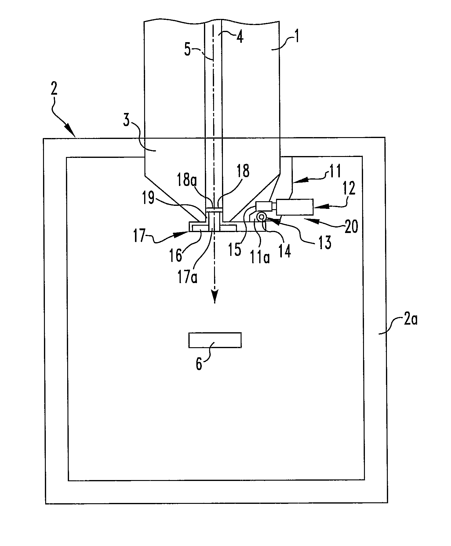
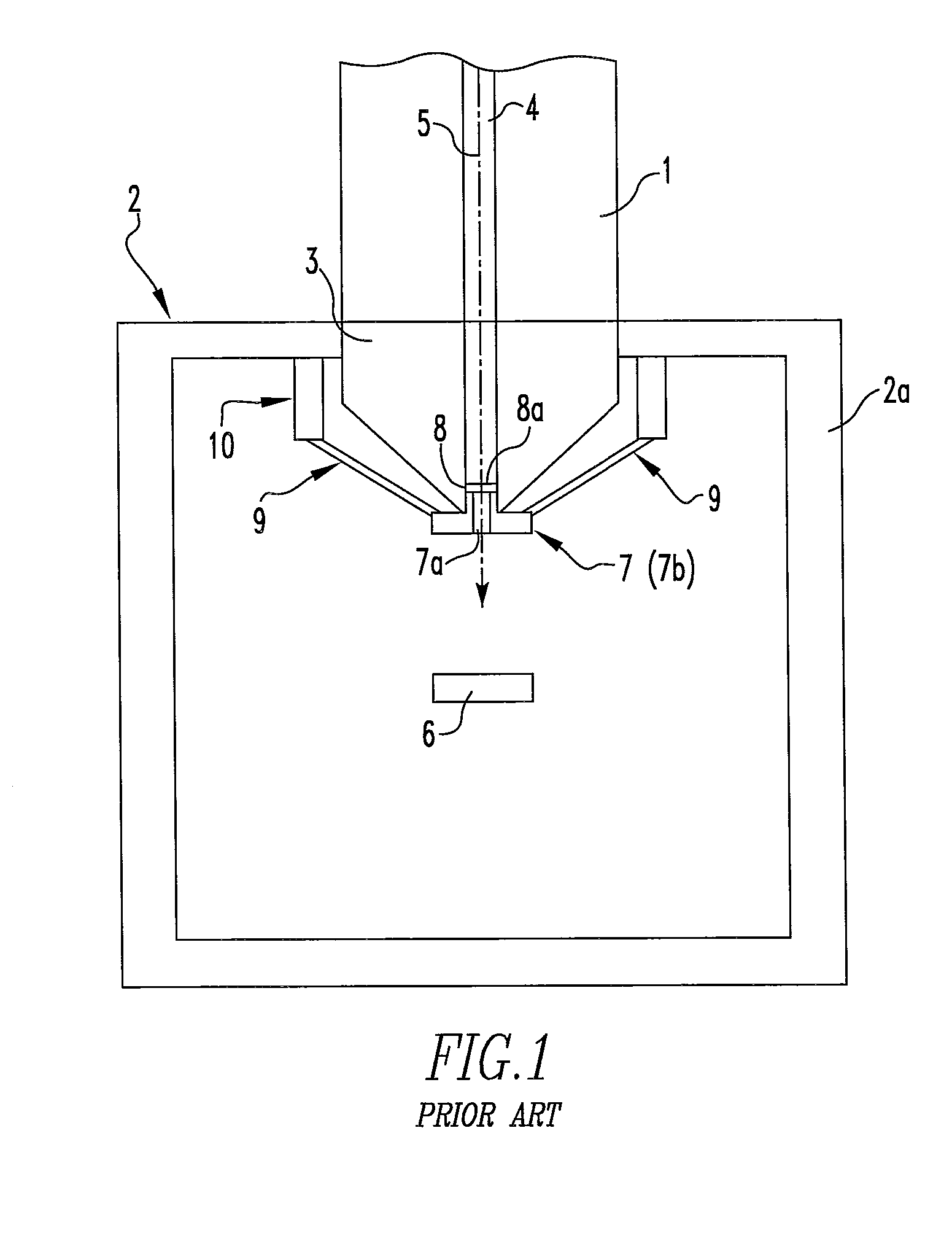
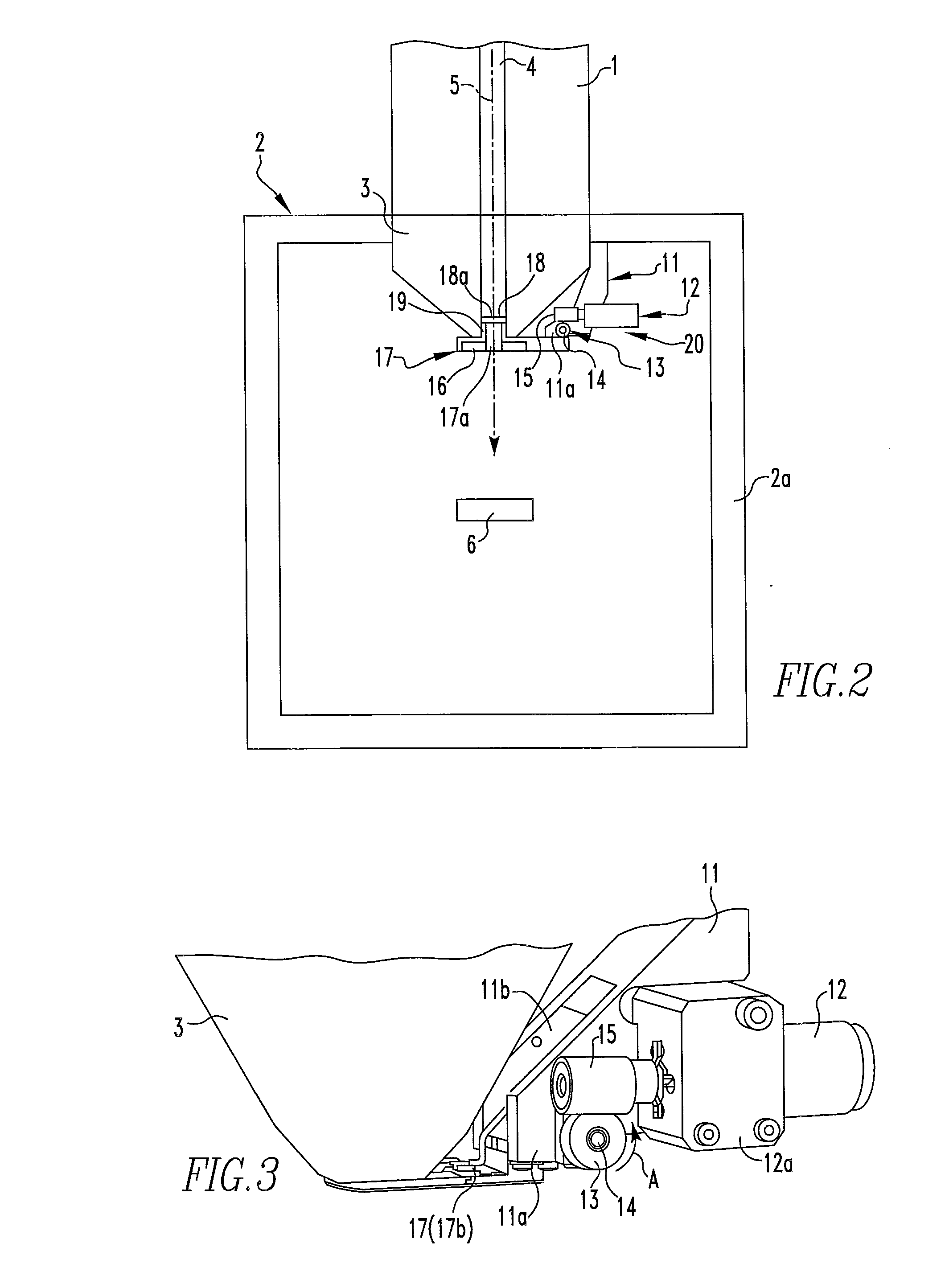
[0034]The preferred embodiments of the present invention are hereinafter described with reference to the drawings. FIG. 2 is a schematic cross section of main portions of a scanning electron microscope, according to the present invention, the microscope having low-vacuum imaging capabilities. Note that in both FIGS. 1 and 2, like components are indicated by like reference numerals.

[0035]Referring to FIG. 2, a beam passage 4 through which an electron beam 5 passes is formed in an electron optical column 1. The passage 4 is made of a tubular passageway. The beam 5 traveling in the passage 4 is released from the front end (i.e., the front end of an objective lens 3) of the electron optical column 1 via the objective lens 3 disposed in a front-end portion of the column 1.

[0036]An electron gun (not shown) acting as an electron beam source is equipped on the base-end side of the electron optical column 1. The gun emits the electron beam 5 by a given accelerating voltage. The beam 5 releas...


PUM


Abstract

An electron beam apparatus has the electron optical column for releasing an electron beam from the front-end portion after the beam is emitted from an electron beam source located on a rear-end portion of the column, a specimen chamber connected to a front-end portion of the column, and an aperture member withdrawably disposed in the front-end portion of the column within the specimen chamber. The apparatus further includes a rotating mechanism for rotating the aperture member along a given plane lying along the direction of a path of the beam. Thus, the aperture member can be attached and detached to and from the front-end portion of the column.

Description

BACKGROUND OF THE INVENTION[0001]1. Field of the Invention[0002]The present invention relates to an electron beam apparatus, such as a scanning electron microscope enabling imaging of a specimen under low-vacuum condition.[0003]2. Description of Related Art[0004]FIG. 1 is a schematic cross section of main portions of a scanning electron microscope capable of low-vacuum imaging of specimens. In FIG. 1, the microscope has an electron optical column 1 where there is formed a beam passage 4 through which an electron beam 5 travels. The passage 4 is a tubular passageway. The beam 5 transmitted through the passage 4 is released from the front end of the electron optical column 1 via the front end of an objective lens 3 disposed in a front-end portion of the electron optical column 1. An electron gun acting as an electron beam source, deflection coils, and other components (none of which are shown) are mounted in the column 1.[0005]The front-end portion of the electron optical column 1 is ...

Claims


Application Information

Patent Timeline
IPC IPC(8): H01J37/26
CPCH01J37/023H01J37/09H01J37/244H01J2237/2605H01J2237/188H01J2237/24475H01J37/28
Inventor YOSHIKAWA, MITSUTOSHI
Owner JEOL LTD
Why Eureka
Try Eureka