LED lamp device

a technology of led lamps and lampshades, which is applied in the direction of lighting and heating apparatus, instruments, process and machine control, etc., can solve the problems of large dimension of products having the same, large power consumption of fluorescent lamps or halogen lamps, etc., and achieves the effects of reducing power consumption, reducing energy consumption, and simplifying configuration

Inactive Publication Date: 2011-01-13
SHIM HYUN SEOP
View PDF2 Cites 58 Cited by
  • Summary
  • Abstract
  • Description
  • Claims
  • Application Information

AI Technical Summary

Benefits of technology

[0041]The present invention as described above has advantageous effects in that the inputted power can be converted from the AC to the DC through a simplified configuration in which a proper number of the LEDs connected with a bridge rectifier circuit are arranged. Further, since the luminance of the LED lighting is automatically or manually controlled by a dimming part in response to the luminance of the inside or outside of a room, a noise level or the like, it has effects in that energy wasting factors can be resolved by reducing the power consumption due to the driving of the LED illuminating lamp, and further an economical LED lamp device can be obtained. Moreover, the present invention with the simplified construction as the above has advantageous effects in that since the manufacturing costs are reduced and the dimension of the product is miniaturized, the sales efficiency can be facilitated by reduction of the sales cost of the product, and the application range of the product can be expanded due to the miniaturization of the product.
[0042]Particularly, the present invention has advantageous effects in that it can cut off or control the loads in the circuit against an over-voltage and an over-current, so as to ensure a safe and a stable use of the LED illuminating lamp to obtain a user's credibility on the product.
[0043]F

Problems solved by technology

However, such a fluorescent lamp or halogen lamp still consumes lots of power compared with the general indoor illuminating lamp, mainly providing illumination in a single color.
At this point, the A/D converter is accompanied by a transformer circuit havi

Method used


Image

  • LED lamp device
  • LED lamp device
  • LED lamp device

Examples


embodiment 1

Another Embodiment 1

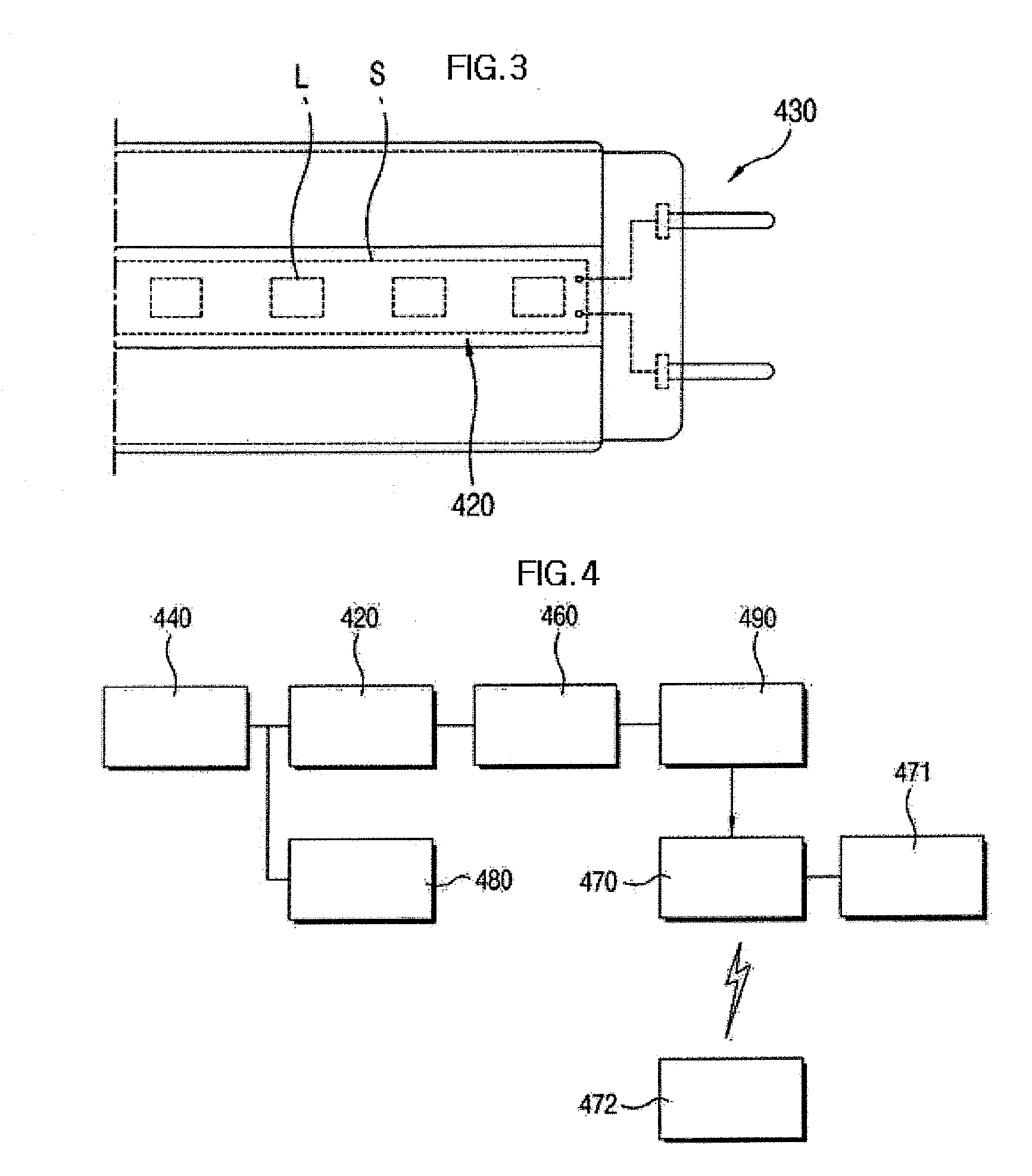
[0103]FIG. 9 is a perspective view illustrating another embodiment 1 of the present invention, FIG. 10 is an enlarged perspective view illustrating another embodiment 1 of the present invention, FIG. 11 is a cross-sectional view illustrating another embodiment 1 of the present invention, FIG. 12 is an enlarged plan view illustrating a terminal part in accordance with another embodiment 1 of the present invention, and FIG. is a block diagram illustrating a circuit unit in accordance with another embodiment 1 of the present invention.

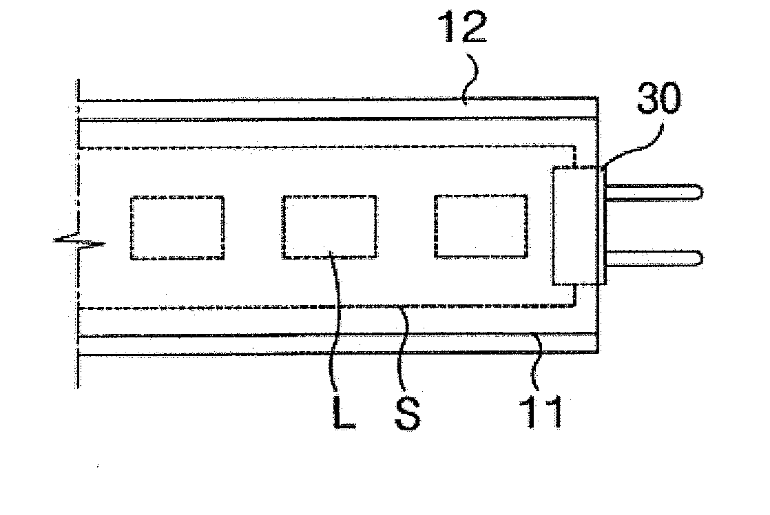
[0104]Referring to the drawings, an LED lamp device in accordance with another embodiment 1 of the present invention typically includes a luminescent body 10, a circuit unit 20, and a terminal part 30.

[0105]The luminescent body 10 is a construction to be an exterior decor of an illuminating lamp, and consists of a base 11 having a heat radiating function and a transmitting body12 for diffusing and transmitting the light emitted from th...

embodiment 2

Another Embodiment 2

[0127]Meanwhile, another embodiment 2 of the present invention will be described in detail with reference to the accompanying drawings.

[0128]FIG. 15 is a perspective view illustrating another embodiment 2 of the present invention, and FIG. 16 is an enlarged cross-sectional view illustrating another embodiment 2 of the present invention.

[0129]Referring to the drawings, an LED illumination device in accordance with another embodiment 2 is composed of a LED illuminating lamp 110 and a lens 120 disposed within the LED illuminating lamp 110. At this point, the LED illuminating lamp 110 whose overall exterior shape is in the form similar to that of a fluorescent lamp can be installed to the ordinary socket for the fluorescent lamp provided inside or outside of the building, which can be applied as an indoor lighting.

[0130]Specifically, the LED illuminating lamp 110 consists of a base 130 having a heat radiating function and a light transmitting cover 140 for diffusing ...

embodiment 3

Another Embodiment 3

[0156]FIG. 23 is an enlarged cross-sectional view illustrating another embodiment 3 of the present invention.

[0157]Referring to the drawing, the LED lamp device of another embodiment 3 of the present invention is composed of a socket 201 and an LED module 202. Here, the socket 201 is electrically connected to an external power line and designed to have internal wirings in order to input an AC power to the LED module 202.

[0158]The LED module 202 is formed with a screw fitting part 204 at one side which is correspondingly coupled with a screw fitting hole 203 of the socket 201 so as to be electrically coupled with the socket 201. The LED module 202 as such is configured in a bulb shape which enables the LED elements 231 to emit light upon receiving the AC power source 211.

[0159]For this purpose, the LED module 202 is constructed to include a case 205 formed with the screw fitting part 204 at one side while maintaining a bulb shape, and a circuit unit mounted on a p...


PUM


Abstract

This invention relates to an LED lamp device which can be applicable to a socket of a general fluorescent lamp, a halogen lamp, an incandescent lamp or the like by embodying an LED illuminating lamp powered by an alternating current (AC) through a simplified rectifier circuit and control of the number of LEDs without a dedicated circuit such as SMPS or the like when constructing the illuminating lamp using the LEDs, and which can reduce manufacturing costs and miniaturize the size of a product.

Description

TECHNICAL FIELD The present invention relates to an LED lamp device.[0001]More particularly, this invention relates to an LED lamp device which is applicable to a socket for a general fluorescent lamp, a halogen lamp, a incandescent lamp or the like by embodying an LED illuminating lamp powered by an alternating current (AC) through a simplified rectifier circuit and control of the number of LEDs without a dedicated circuit such as SMPS or the like, when constructing an illuminating lamp using the LEDs, and which can reduce manufacturing costs and miniaturize the dimension of a product. Further, this invention relates to an LED lamp device powered by an AC power source in which an intensity of illumination of the LED illuminating lamp can be automatically or manually controlled in response to the luminance of the inside or outside of a room, a noise level or the like, thereby enabling the illuminating device to be operated with less power, and which is capable of being operated safe...

Claims


Application Information

Patent Timeline
IPC IPC(8): H05B37/02F21V5/00F21V5/04
CPCF21K9/17F21V29/89F21Y2101/02F21Y2103/003H05B33/0803H05B33/0812Y02B20/343Y02B20/383Y02B20/386F21V29/20F21K9/13F21Y2111/004F21K9/135F21V29/76F21V5/08F21K9/23F21K9/232F21K9/27F21Y2103/10F21Y2115/10F21Y2107/20F21K9/69F21V5/10F21V29/763Y02B20/30H05B45/3578H05B45/30H05B45/395H05B45/325H05B45/357
Inventor SHIM, HYUN-SEOP
Owner SHIM HYUN SEOP
Why Eureka
Try Eureka