
Apparatus and Method for Providing Information Relating to a Motor

a technology of information and apparatus, applied in the direction of motor/generator/converter stopper, electronic commutator, dynamo-electric converter control, etc., can solve the problems of less than 5% of the rated speed of the motor, and prior art techniques cannot work properly at zero speed, so as to achieve the effect of extracting more information

Inactive Publication Date: 2011-01-13
CITY UNIVERSITY OF HONG KONG
View PDF10 Cites 18 Cited by
  • Summary
  • Abstract
  • Description
  • Claims
  • Application Information

AI Technical Summary

Benefits of technology

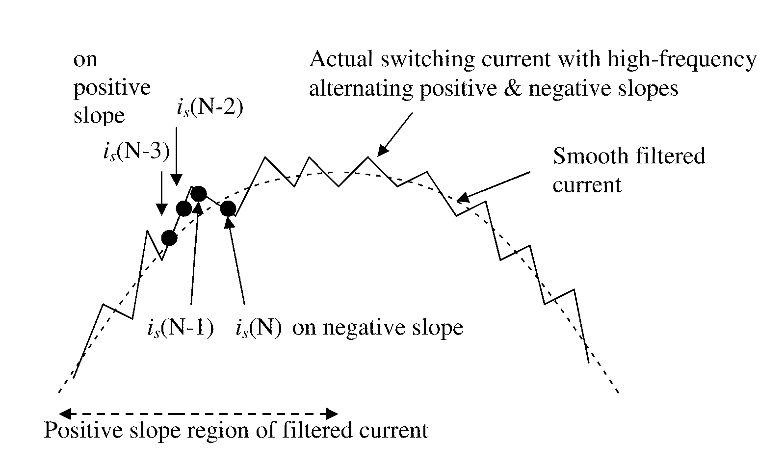
[0019]Preferably the apparatus is arranged so that the processor determines the instantaneous rate of change of the motor current based on instantaneous motor current is samples which are not filtered, or which are filtered by a filter which retains peaks and troughs caused by switching of the inverter. The filter may be a digital filter which is implemented by a processor (e.g. the controller of the motor). The filter does not produce a smooth, filtered current (e.g. in the form of a sinusoidal wave), but lets pass switching ripples due to switching of the inverter. It may filter out current spikes which are considerably higher than expected due to switching ripples (i.e. switching ripples are retained and noise spikes filtered out). In this way valuable information is retained but background noise may be filtered out.
[0021]There may be a plurality of samplers arranged for sampling the instantaneous motor current in a plurality of phases. For example two separate sampling devices may be used to sample two of the phases and output to the processor. The processor calculates the motor position or motion information based on measurements of the instantaneous current in said at least two phases. The processor may calculate the instantaneous current in a third phase from the first two phases and the instantaneous rate of change of the current in the third phase also. In this way information from three phases may be utilized with the minimum of hardware. Furthermore, if there is an unexpectedly large difference between the samples in the two phases, or if one or more samples are significantly different to what was expected, based on samples in previous periods, they may be discarded. In this way noise can be reduced.
[0023]The processor may be arranged to calculate the position or motion information based on an artificial motor constant which is lower than the actual motor constant of the motor. This enables more information to be collected, especially at low or zero motor speeds. For example, where a stepped down version of the back emf is used, typically the stepped down version is a function with the motor constant in the denominator. Therefore by using an artificially low motor constant, more information can be extracted.

Problems solved by technology

In the prior art techniques the current ripples are filtered out.2. The prior art techniques cannot work properly at zero speed and, in some cases, speeds less than 5% of the rated speed of the motor.

Method used


Image

  • Apparatus and Method for Providing Information Relating to a Motor
  • Apparatus and Method for Providing Information Relating to a Motor
  • Apparatus and Method for Providing Information Relating to a Motor

Examples


Embodiment Construction

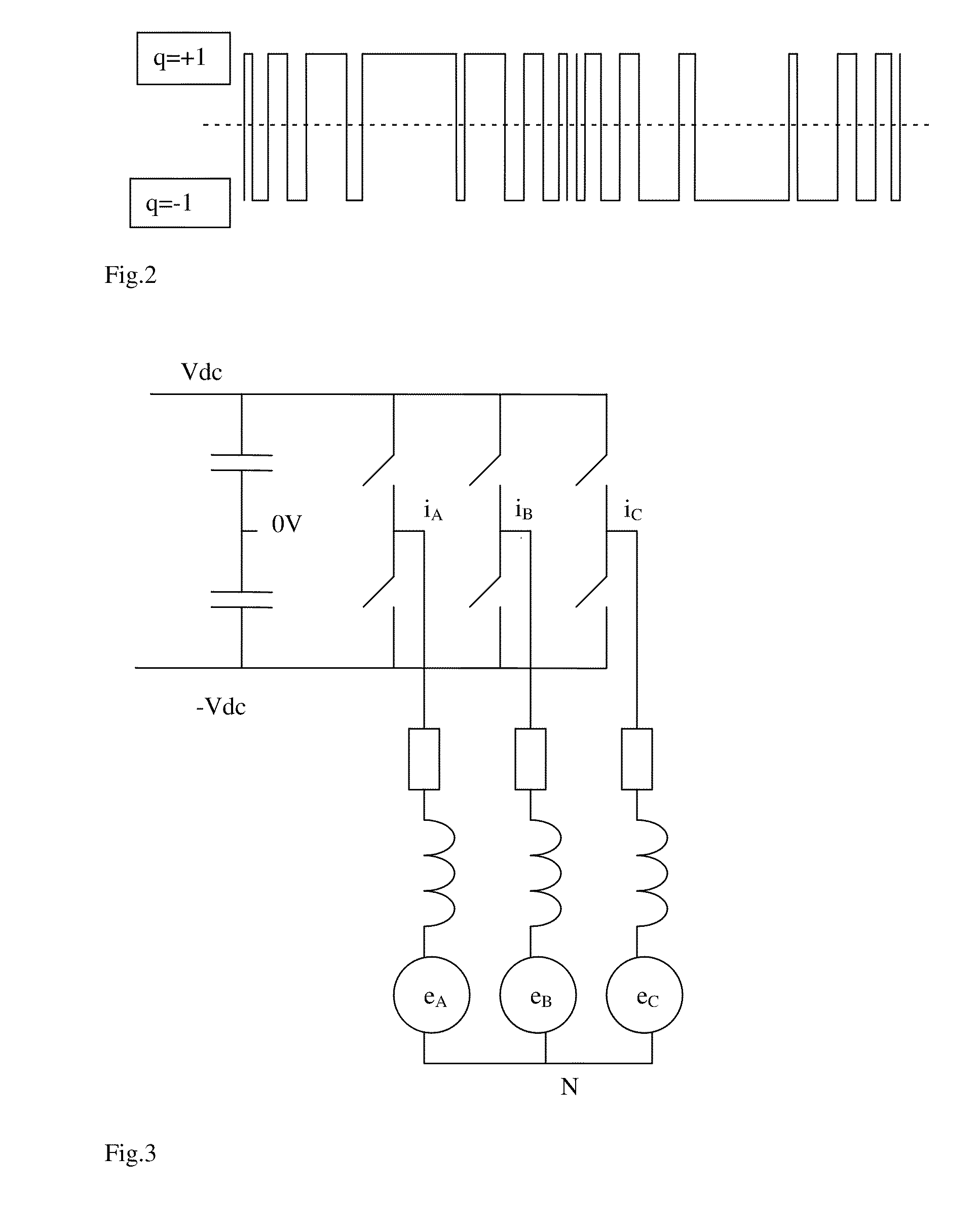
[0042]The basic concept underlying embodiments of the invention is first illustrated with a per-phase equivalent circuit of a motor. The application of the concept to a multiphase motor will be described later.

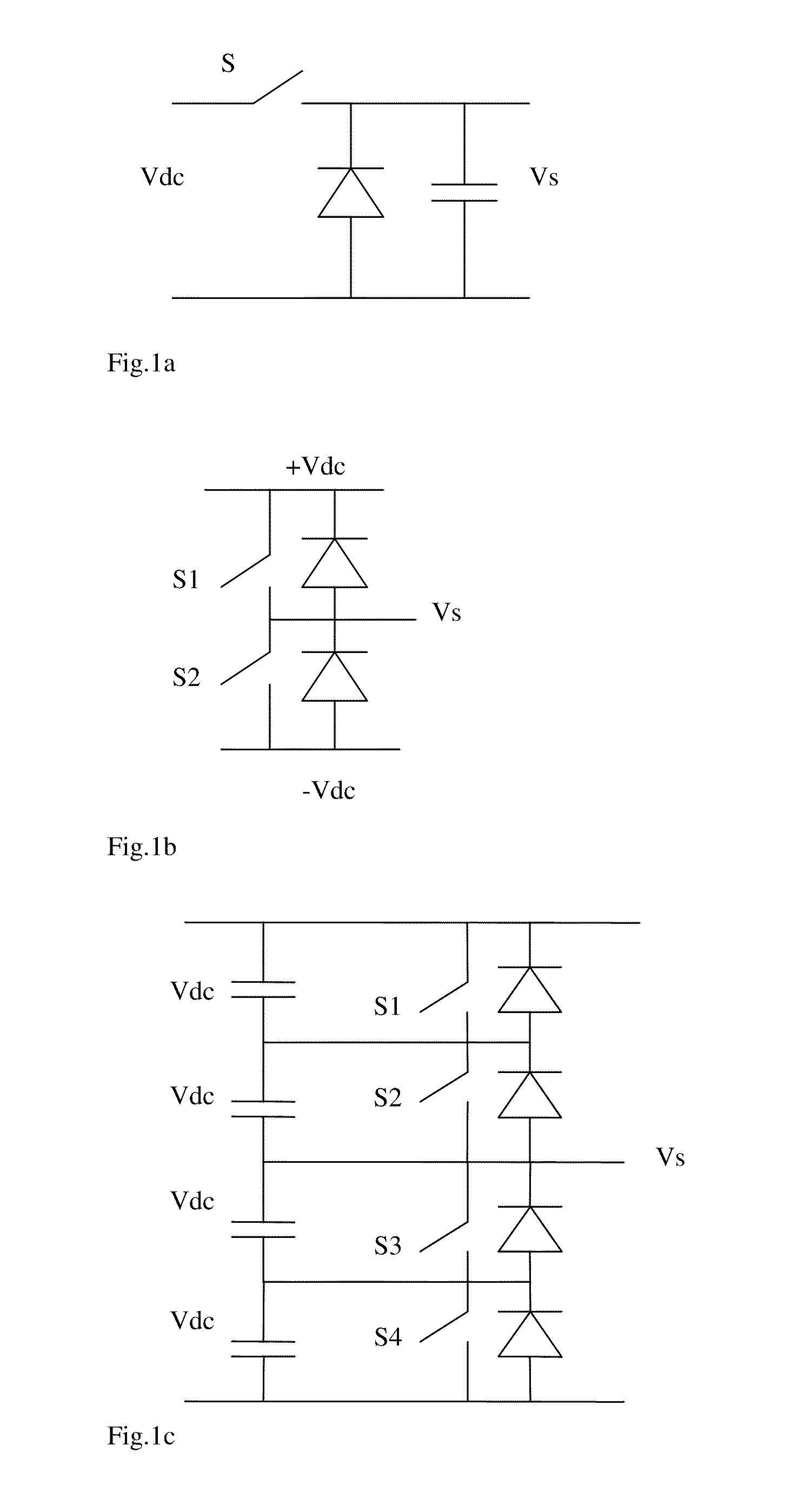
[0043]FIG. 1(a) shows a dc-dc chopper circuit that is commonly used for driving dc motors. When the switch (S) is turned on, the output voltage (Vs) for driving the motor is Vdc. When the switch is turned off, the motor current will flow through the diode so that the converter output voltage is zero. Thus, the output voltage of the chopper circuit is:

Vs=q.Vdc   (1)

where q=[0,1]

[0044]FIG. 1(b) shows one power inverter leg. S1 and S2 are switched in a complimentary manner. That is, when S1 is turned on, S2 is turned off, and vice versa. The output voltage of this inverter leg can be expressed as:

For 2-level power inverter,

Vs=qVdc   (2)

where q=[−1, +1]

[0045]A 3-level inverter is shown in FIG. 1(c). With appropriate control of the four switches S1 to S4, the output voltage can be:...


PUM


Abstract

This invention relates to an apparatus and method for deriving speed and position information for an electric motor. Apparatus for and a method of controlling a motor 100 are also disclosed. The apparatus for providing information relating to the operation of an electrical motor 100 comprises a sampler 50, 51 for sampling the instantaneous motor current is and a processor 160 for determining the instantaneous rate of change of the motor current and providing information about the motion or position of said motor based on said instantaneous rate of change of the motor current. In this way speed and position information can be provided, at low speeds, and without using a speed sensor.

Description

FIELD OF THE INVENTION[0001]This invention relates to methods and apparatus for providing information relating to operation of a motor and electronic control of motor drives. In particular, methods and apparatus that do not require the use of speed and position sensors.BACKGROUND OF THE INVENTION[0002]Most electrical motors are driven by power electronic circuits such as power inverters. Modern electronic motor drives require accurate information of motor speed for control purposes. Traditionally, speed sensors are mounted on the motor shaft so as to provide speed information for control purposes. However, the use of speed sensors not only increases the cost of the drive system, it also reduces the reliability of the motor drive system. In addition, the extra requirements for a shaft extension and mounting arrangement of the speed sensor make it unattractive to use speed sensors. Reliability of speed sensors is an issue particularly in hostile working environments where wide tempera...

Claims


Application Information

Patent Timeline
IPC IPC(8): H02P6/18
CPCH02P6/007H02P2203/09H02P27/08H02P6/18
Inventor HUI, SHU YUEN RON
Owner CITY UNIVERSITY OF HONG KONG
Learn More