
Power array for high power pulse load

a power array and pulse load technology, applied in the direction of electric variable regulation, process and machine control, instruments, etc., can solve the problems of reducing the current delivery capability of the supply source, severe demand on the system power supply, and high radio frequency interference rfi which is reflected, so as to reduce the number of inoperative pulse loads and efficient to independent operation of each pulse load

Active Publication Date: 2011-01-13
ELTA SYST LTD
View PDF13 Cites 13 Cited by
  • Summary
  • Abstract
  • Description
  • Claims
  • Application Information

AI Technical Summary

Benefits of technology

[0043]It is a further object to provide such a power supply array which lends itself more efficiently to independent operation of each pulse load so as to reduce the number of inoperative pulse loads in the event of a faulty switch power supply.

Problems solved by technology

However, the sudden current surges thus consumed when the antenna element becomes active place a severe demand on the system power supplies.
Conventional solutions using switching mode power supplies for such a load struggle to avoid the output voltage dropping during the transmission pulse and reflecting the load power requirements to the main system power supplies.
The ripple current in the current supplied by the main power supply can cause high radio frequency interference RFI which is reflected on to the main supply source if it is not suppressed.
Maintaining the ripple current as low as possible also diminishes the conduction losses related to high root mean square (RMS) current values, which reduce the current delivery capability of the supply source.
However, when a switch power supply is used in conventional circuits for supplying power as intermittent current bursts, the sudden current burst reflects on the line causing sudden and intermittent voltage reductions on the line.
When very high power bursts are being supplied, the RFI filter becomes bulky and expensive.
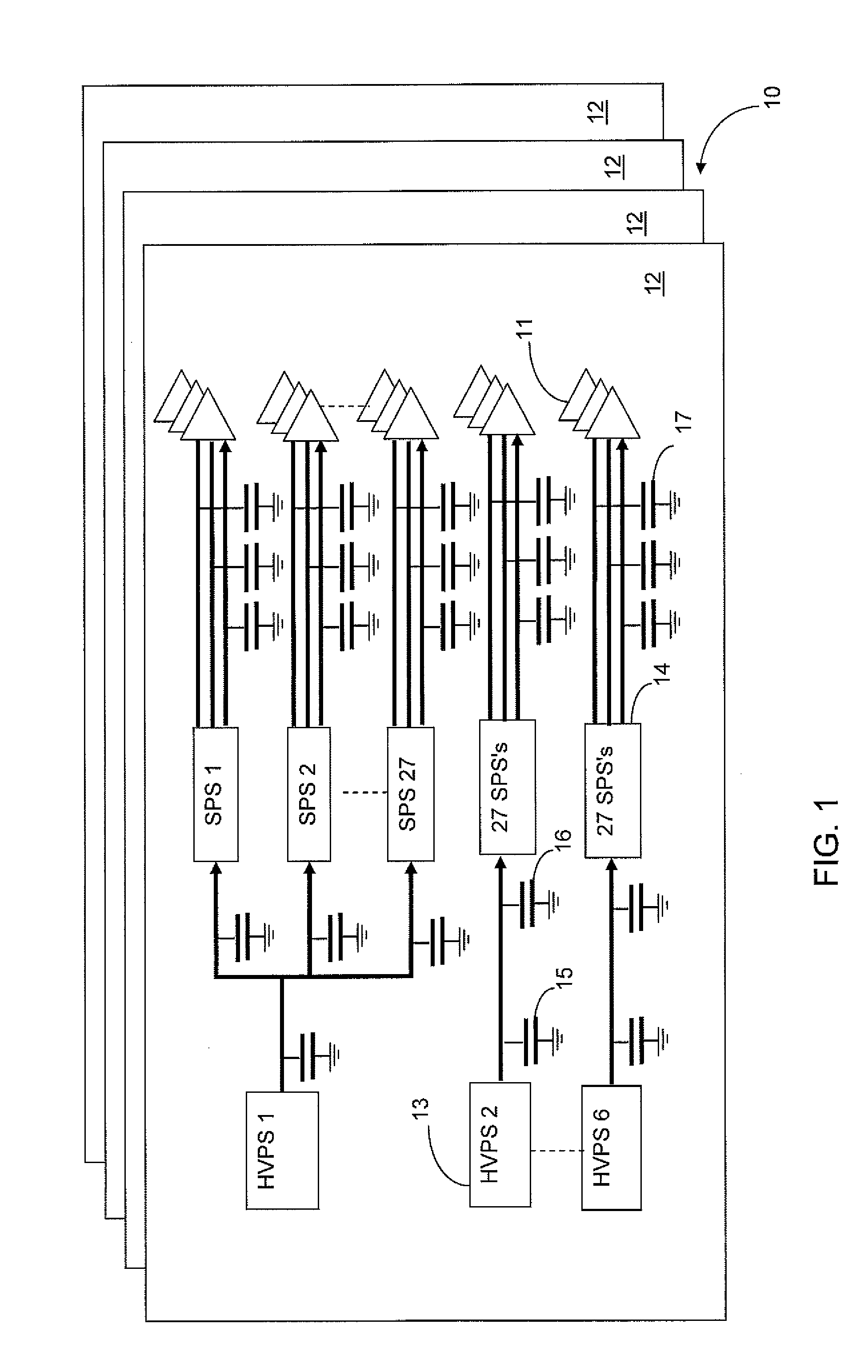
Yet a further drawback with such a circuit topology where 16 antenna elements are powered by each switch power supply 14 is that failure of a switch power supply 14 results in 16 antenna elements becoming inoperative and this, of course, may impact adversely on the magnitude and shape of the antenna beam.
However, while this reduces the adverse effect of such a failure it still results in multiple antenna elements becoming inoperative in the event of a failure in a switch power supply 14.

Method used


Image

  • Power array for high power pulse load
  • Power array for high power pulse load
  • Power array for high power pulse load

Examples


Embodiment Construction

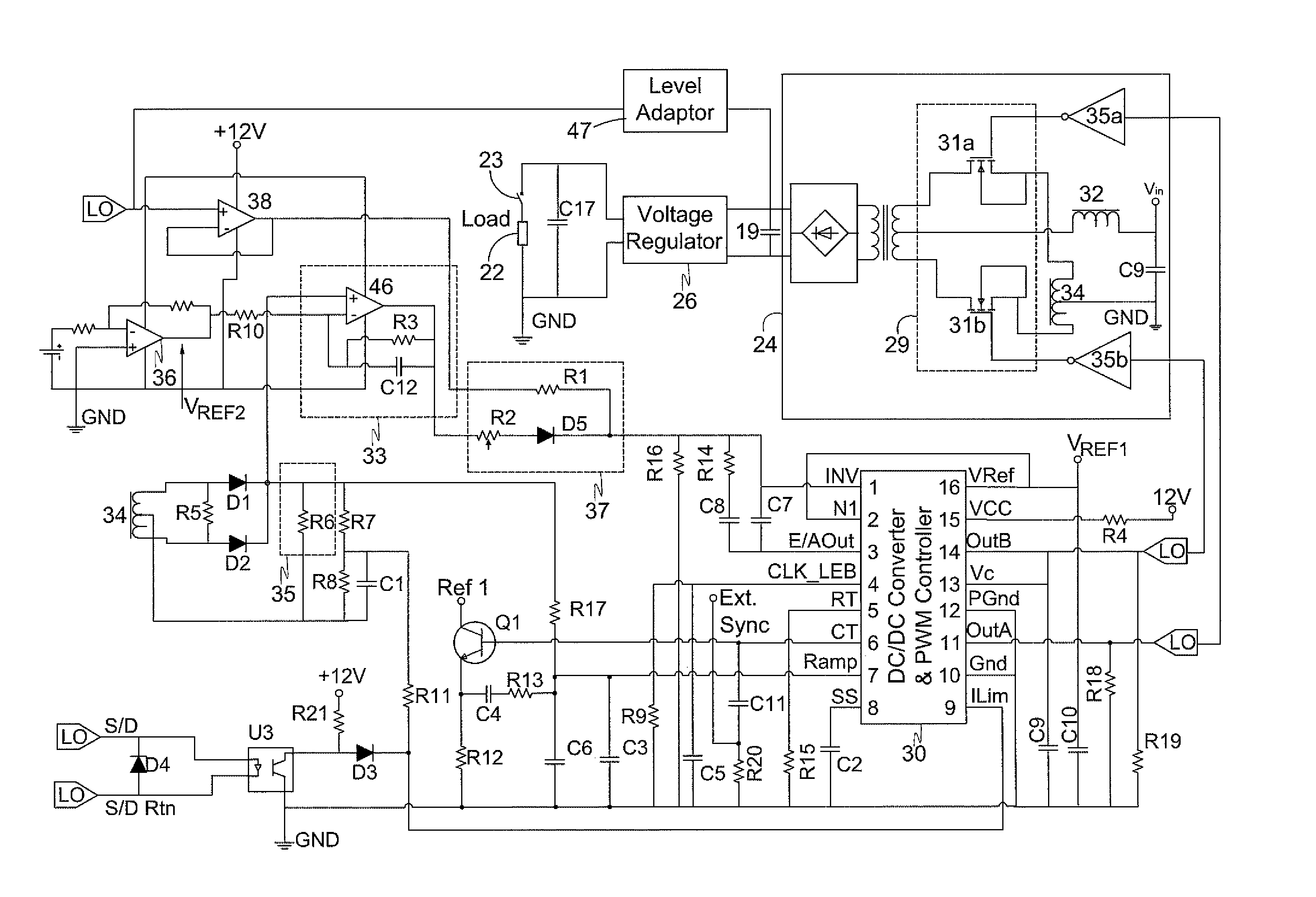
[0066]In the following description of an embodiment of the invention, components that are common to the power supply array 10 described above with reference to FIG. 1 or serve a common function thereto will be identified by identical reference numerals.

[0067]FIG. 3 shows the topology of a power supply array 20 according to the invention for feeding DC power to antenna elements 11 (constituting pulse loads) of a phase array antenna. Thus, here also, four antenna arrays are provided each on a respective wall 12, there being one wall 12 for each surface of the aircraft as explained above. Each wall 12 comprises an array of low voltage current sources 18 that are energized by high voltage power supplies at a voltage of 270V and each of which serves as a constant DC current source for feeding constant current at a nominal voltage of 70V to a respective storage capacitor 19 each coupled to a plurality of switch power supplies 14. Each of the storage capacitors 19 serves as a voltage reser...


PUM


Abstract

A controlled power supply comprising: a) an array of low voltage current sources; b) a plurality of switch power supplies coupled to each of the storage capacitors and respective ones of the pulse loads being coupled to each of the switch power supplies; c) each of the storage capacitors being configured for storing energy during an inactive portion of a load switching cycle of the respective switch power supply to which the corresponding storage capacitor is coupled when the pulse loads are inactive; d) a respective output capacitor in association with each of the switch power supplies for feeding voltage to the respective pulse loads during an active portion of the load switching cycle; and e) the respective storage capacitor being configured for supplying the stored energy via the respective to the respective switch power supply to which the storage capacitor is coupled to each of the pulse loads coupled to switch power supply during an active portion of the load switching cycle.

Description

FIELD OF THE INVENTION[0001]This invention relates to pulse load switching power supplies that is particularly suitable for use in phased array radar antennas.BACKGROUND OF THE INVENTION[0002]Some types of phased array antennas require that a large numbers of antenna elements be activated simultaneously. This, of course, demands significant power, which is provided by the main system power supplies. The incremental contribution that each antenna element makes to the composite beam is, of course, a feature of the antenna design and so it is possible to determine in advance which antenna elements to energize and at what voltage magnitude in order to achieve a desired beam steering and tracking. Each antenna element is energized according to the pulse width to be transmitted so that there is an instantaneous demand for the time period when the antenna element is active followed by an inactive period when the antenna elements are waiting for the next transmitting pulse. However, the sud...

Claims


Application Information

Patent Timeline
Patent Type & Authority Applications(United States)
IPC IPC(8): H01Q1/00H02J3/14H01Q1/46
CPCH02J1/102H02M3/1584H02M3/07
Inventor BATIKOFF, ENRIQUEZELIG, ROBERT
Owner ELTA SYST LTD
Learn More