Variable frequency drive soft charge circuit

a technology of soft charge circuit and variable frequency drive, which is applied in the direction of ac-ac conversion, power conversion systems, electrical equipment, etc., can solve the problems of significant switching transients, prohibitive surge current, and harmful start-up transients to the system

a technology of soft charge circuit and variable frequency drive, which is applied in the direction of ac-ac conversion, power conversion systems, electrical equipment, etc., can solve the problems of significant switching transients, prohibitive surge current, and harmful start-up transients to the system

US20110007530A1Inactive Publication Date: 2011-01-13YASKAWA ELECTRIC AMERICA

Image

  • Variable frequency drive soft charge circuit
  • Variable frequency drive soft charge circuit
  • Variable frequency drive soft charge circuit

Examples


Embodiment Construction

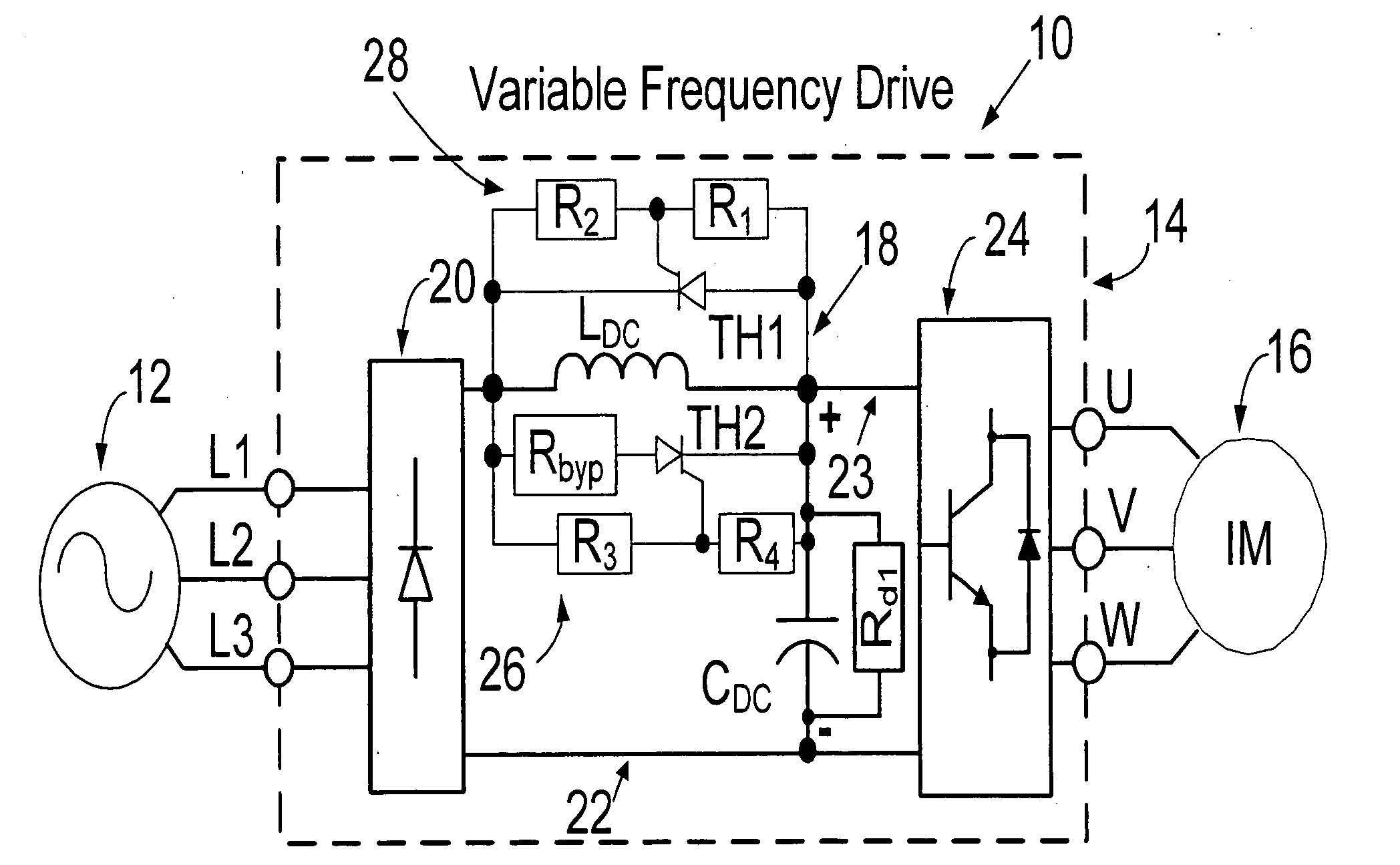
[0030]The present invention uses alternative techniques to soft charge a DC link capacitor. The technique does not use mechanical contactors and should be able to handle brown out conditions in an efficient manner. Autonomous operation is provided, i.e., without any control logic, to handle various power supply conditions. Lastly, the resulting drive unit should be compact and economical. An exemplary topology in accordance with the invention, shown in FIG. 4, generally satisfies these target features. A DC link inductor with a resistor assist circuit is employed to soft charge the DC link capacitor. An assist resistor has a series thyristor.

[0031]Referring particularly to FIG. 4, a motor drive system 10 is illustrated. The motor drive system 10 includes an AC source 12 and a variable frequency drive (VFD) 14 for driving an induction motor 16. As is known, a control unit (not shown) would be used for controlling the variable frequency drive. However, such control unit is not shown h...


PUM


Abstract

A variable frequency drive comprises a diode rectifier receiving multiphase AC power and converting the AC power to DC power. An inverter receives DC power and converts the DC power to AC power to drive a load. A link circuit is connected between the diode rectifier and the inverter and comprises a DC bus to provide a relatively fixed DC voltage for the inverter. A link capacitor is across the bus. A soft charge circuit limits in rush current to the link capacitor. The soft charge circuit comprises an inductor in the bus and a resistor assist circuit across the inductor along with an anti-parallel clamping thyristor reverse connected also across the inductor.

Description

FIELD OF THE INVENTION[0001]The present invention relates to variable frequency drives and, more particularly, to a soft charge circuit including an inductor and a resistor assist circuit.BACKGROUND OF THE INVENTION[0002]AC to DC rectifiers are widely used to convert AC line electric power to DC power to be used by inverters (for motor, UPS, and other applications), DC / DC converters, and passive loads such as resistors. In any rectifier circuit, the AC line voltages are rectified and ripple of the rectified voltage is filtered using a parallel capacitor and occasionally a series inductor. This results in a fixed, i.e., ripple free, DC voltage.[0003]Without appropriate pre-charge circuitry, the start-up transients can be harmful to the systems. If the AC line and / or the DC link filters do not have sufficient impedance, significant switching transient may occur upon closing a three-phase supply switch. A large current surge charges the capacitor and depending on the system impedance, ...

Claims


Application Information

Patent Timeline
13 Jan 2011
Publication
US20110007530A1
IPC
H02M5/45
CPC
H02M5/458; H02M1/36
Inventors
SWAMY, MAHESH M.; KUME, TSUNEO JOE