
Method and apparatus for acquisition, tracking, and sub-microsecond time transfer using weak gps/gnss signals

Active Publication Date: 2011-01-13
MAGELLAN SYST JAPAN
View PDF12 Cites 48 Cited by
  • Summary
  • Abstract
  • Description
  • Claims
  • Application Information

AI Technical Summary

Benefits of technology

[0028]Sub-microsecond time transfer is also obtained using pseudorange measurements from a plurality of satellites acquired by the method described above, so as to obtain position within approximately 100 meters, thereby reducing the time uncertainty to the sub-microsecond level.

Problems solved by technology

Accordingly, it is difficult to establish sub-microsecond time transfer using very weak GPS / GNSS signals suffering severe attenuation, such as those received indoors or in urban canyons.

Method used


Image

  • Method and apparatus for acquisition, tracking, and sub-microsecond time transfer using weak gps/gnss signals
  • Method and apparatus for acquisition, tracking, and sub-microsecond time transfer using weak gps/gnss signals
  • Method and apparatus for acquisition, tracking, and sub-microsecond time transfer using weak gps/gnss signals

Examples


embodiment 1

Accurate Tracking of Previously-Acquired Satellite and Sub-Microsecond Time Transfer

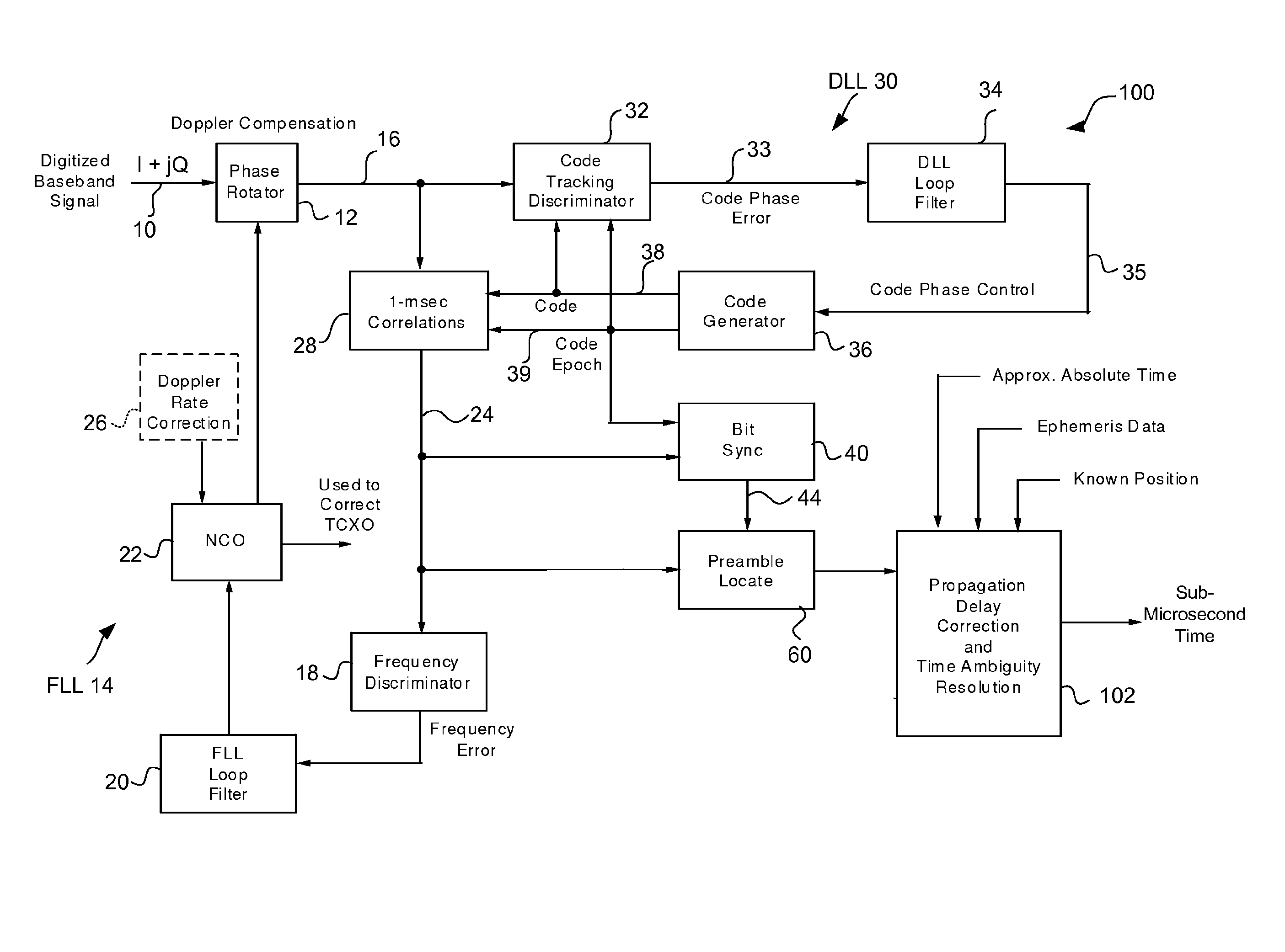
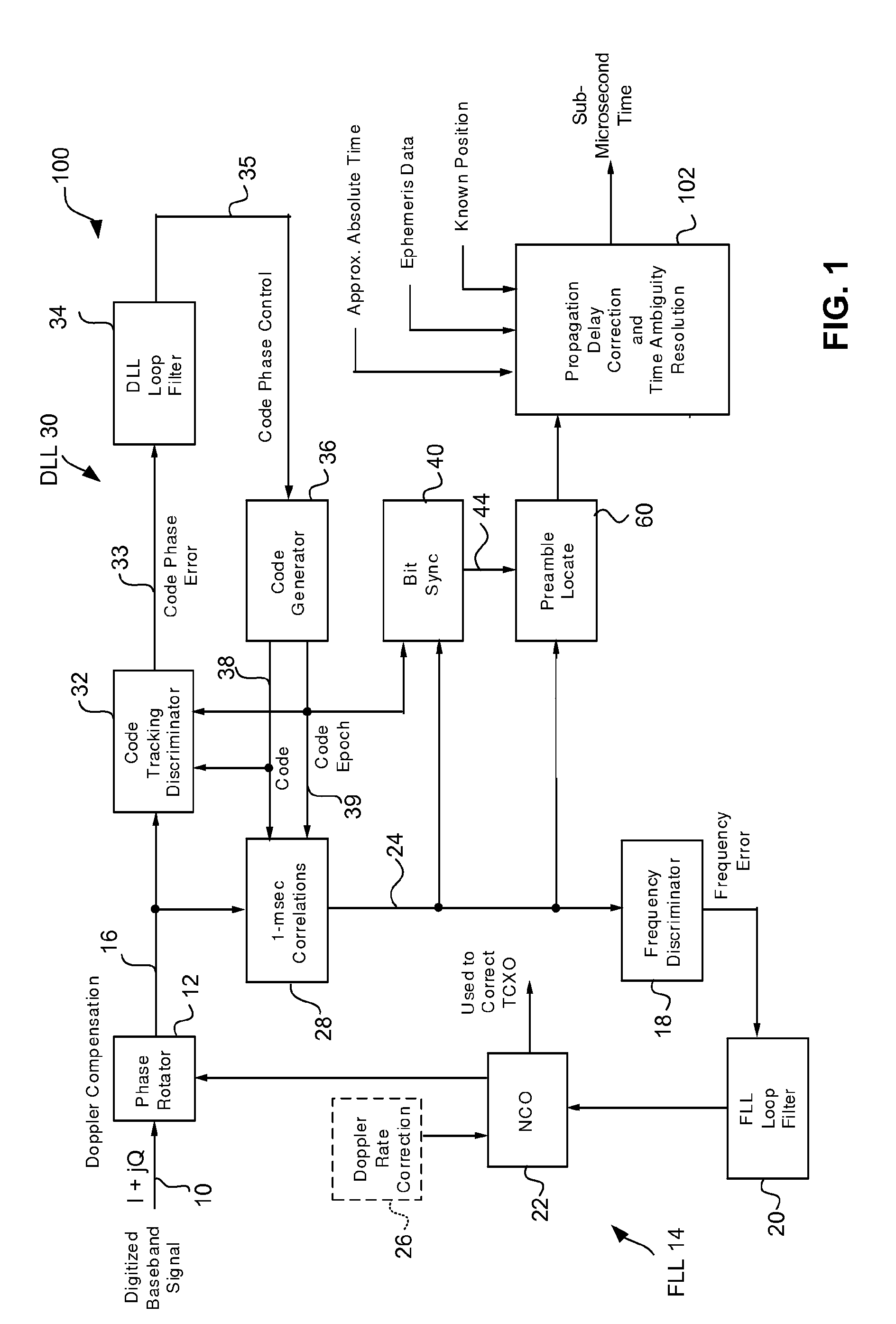
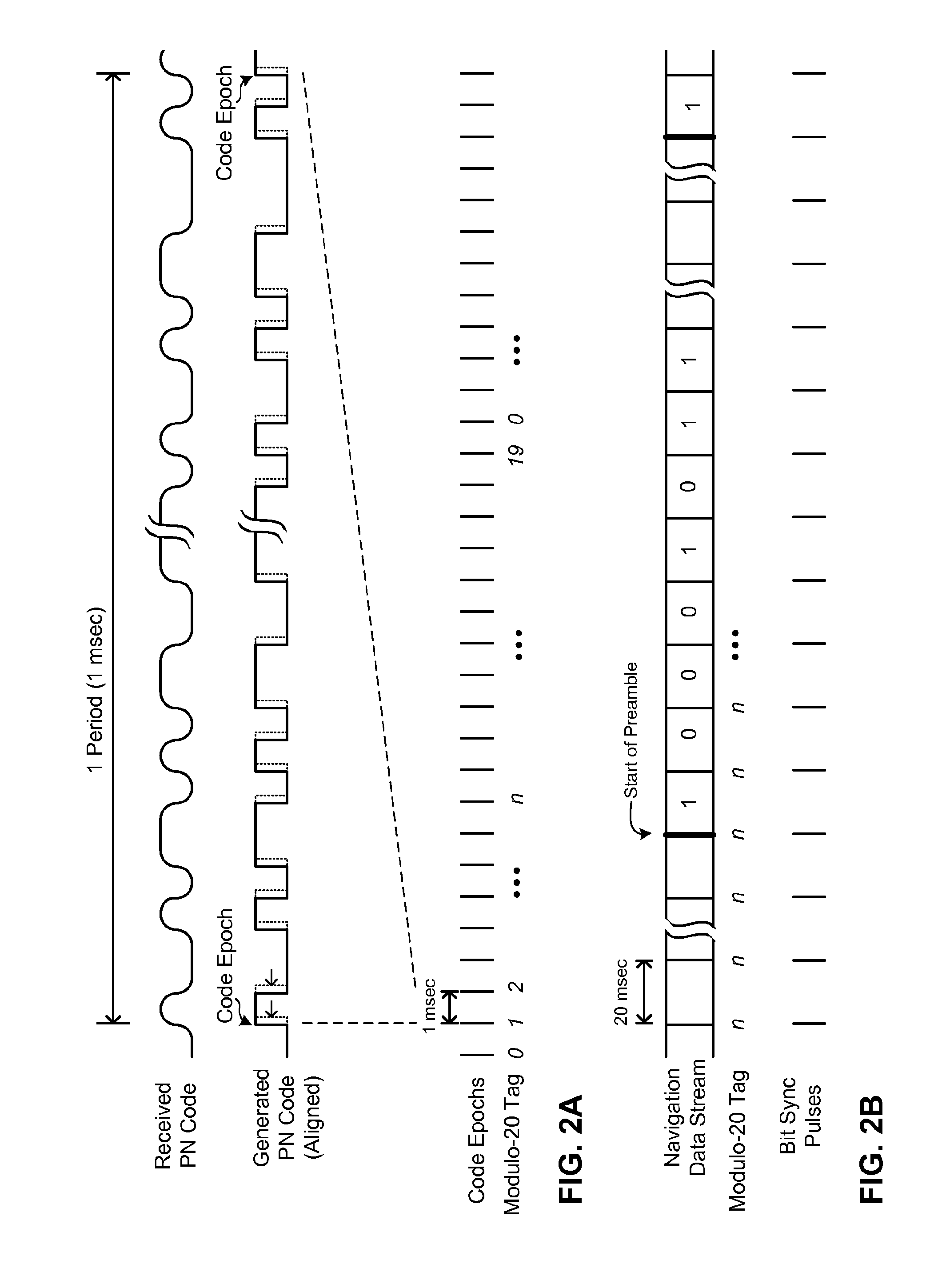
[0084]FIG. 1 is a block diagram schematically illustrating a method and corresponding circuitry 100 for accurate tracking of a previously-acquired satellite and sub-microsecond time transfer using a known receiver position, in accordance with one embodiment of the present invention. If more satellite signals are available, all elements in the figure are replicated for each satellite tracked. FIG. 1 only shows part of a GPS receiver which is able to track a satellite and obtain very accurate time, i.e., sub-microsecond time from a very weak GPS signal. It is assumed that the position of the receiver is known within approximately 100 meters for sub-microsecond accuracy, and that a satellite signal has already been acquired and code and carrier frequency tracking have been initiated. That is, as shown in FIG. 1, the input signal to the circuitry 100 is a digitized baseband signal 10 which is received by...

example 1

Detecting Occurrence of the Subframe Preamble

[0099]FIG. 4 schematically illustrates the frame and subframe structure of the GPS navigation data stream. A complete navigation data message consists of 25 frames, each containing 1500 bits transmitted at a 50 bit / sec rate. Each frame is subdivided into five 300-bit subframes (#1 through #5 in FIG. 4), each subframe consisting of 10 words of 30-bits each, with the most significant bit (MSB) transmitted first. Thus, at the 50 bits / sec rate, it takes 6 seconds to transmit a subframe, and 30 seconds to complete one frame. Transmission of the complete 25-frame navigation message requires 750 seconds, or 12.5 minutes. Except for occasional updating, subframes #1, #2, and #3 are mostly constant (i.e., repeat) with each frame at the 30 second frame repetition rate. On the other hand, subframes #4 and #5 are each subcommutated 25 times. The 25 versions of subframes #4 and #5 are referred to as pages 1-25. Hence, except for occasional updating, e...

example 2

Detecting the Occurrence of a Larger Segments of Bits

[0112]FIG. 7 schematically illustrates an alternative way of obtaining signal transmission time, in accordance with another embodiment of the present invention, which detects the occurrence of larger segments of data bits in the navigation message. In FIG. 7, the like elements bear the like reference numerals as those in FIG. 1. As shown in FIG. 7, the circuitry 120 includes a target segment locator 80 in place of the preamble locator 60 in FIG. 1. Since it is assumed that satellite ephemeris data, satellite clock correction data, almanac data, and perhaps other data, such as Time of Week (TOW), in the navigation message is available from an external source, this information can be used to determine the bit sequences that are used to transmit it. Since the position of these known bit sequences relative to the start of a frame is known, the occurrence of the first bit at the start of a frame can also be determined from the detected...


PUM


Abstract

A method and apparatus provide high-sensitivity GPS / GNSS signal acquisition in a stationary GPS / GNSS receiver. The uncertainty in frequency due to apparent Doppler shift is partitioned into a plurality of contiguous frequency bins, and the uncertainty in location of navigation data bit boundaries is partitioned into equally spaced trial bit boundary locations. For each combination of the trial bit boundary location and the frequency bin, a signal block of captured complex baseband signal is Doppler-compensated using a phase rotator, and then synchronously summed with a periodicity of one period of C / A code so as to produce a compressed sample block having N samples. Each compressed sample block is cross-correlated with one period of reference C / A code to produce an N-value correlation function. A predetermined number of magnitudes of the N-value correlation functions are stack-accumulated into an array with precession compensation so as to find a correlation peak having the largest value.

Description

BACKGROUND OF THE INVENTION[0001]The present invention relates to GPS / GNSS receivers. More specifically, the present invention relates to acquisition, tracking, and sub-microsecond time transfer in GPS / GNSS receivers using weak GPS / GNSS signals.[0002]The use of GPS / GNSS signals for time transfer at the sub-microsecond level is a well-established art. However, most conventional methods depend on the ability of a GPS / GNSS receiver to accurately demodulate timing information from the received GPS / GNSS signal. This implies that the signal must be strong enough to keep the demodulated bit error rate acceptably small (for example, less than about 10−5), which can be guaranteed only if the received signal power is above approximately −148 dBm. Accordingly, it is difficult to establish sub-microsecond time transfer using very weak GPS / GNSS signals suffering severe attenuation, such as those received indoors or in urban canyons.BRIEF DESCRIPTION OF THE INVENTION[0003]The embodiments of the i...

Claims


Application Information

Patent Timeline
IPC IPC(8): H04B1/707G01S19/25G01S19/30
CPCG01S19/254G01S19/30G01S19/258
Inventor WEILL, LAWRENCE R.
Owner MAGELLAN SYST JAPAN
Learn More