Dose reduction and image enhancement in tomography through the utilization of the objects surroundings as dynamic constraints
a dynamic constraint and dose reduction technology, applied in the field of tomography, can solve the problems of not fully using dynamic information about the patient's surroundings, and it is not clear how this information can be utilized by reconstruction algorithms in an effective manner, so as to reduce the number of projections or fluxes needed, the effect of increasing the scan speed
- Summary
- Abstract
- Description
- Claims
- Application Information
AI Technical Summary
Benefits of technology
Problems solved by technology
Method used
Image
Examples
example 1
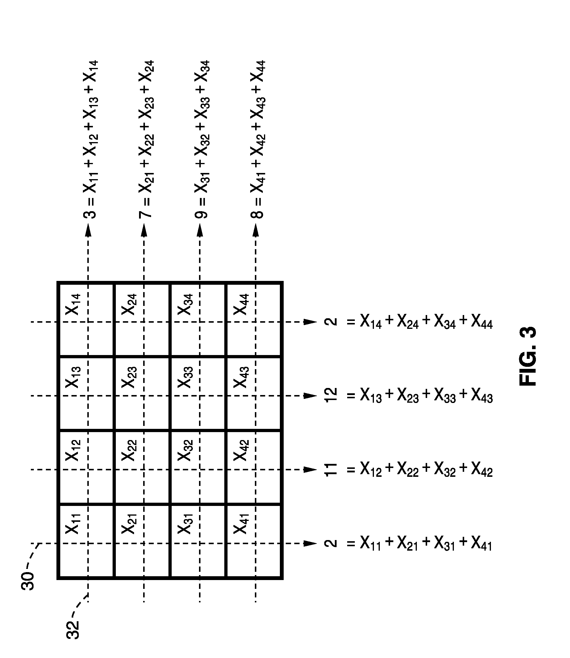
[0071]In order to demonstrate the general principles behind using the patient's surroundings in tomographic scan reconstruction, a simple set of voxels is used. Referring to FIG. 3, the image from a typical tomographic imaging modality is depicted as a set of 16 voxels with unknown values. The dashed arrows 30 and 32 in each row and column represent the vertical and horizontal projections respectively that are acquired experimentally. The projections 30, 32 in many modalities can be considered mathematically as a Radon transform, or a mathematical sum of the translated voxel. The image reconstruction process can then be considered as solving for the 16 voxels through the eight equations provided by the projections as illustrated in FIG. 3.
[0072]Mathematically it is not possible to solve for these 16 voxels with just eight equations, hence more equations relating the voxels, i.e. projections, are needed to solve the system. The number of projections must be increased resulting in a h...
example 2
[0074]Referring now to FIG. 5A and FIG. 5B, a MicroCT scan of a mouse is used to demonstrate an embodiment of the present invention. FIG. 5A and FIG. 5B depict a reconstruction of a mouse in a MicroCT scanner through conventional methods. The image depicted in FIG. 5A is a coronal view of the reconstruction and the image depicted in FIG. 5B is one transaxial slice of a typical reconstruction of the same mouse. In these scans, the mouse was placed in a cylindrical casing 40 on a platform 42. The mouse is naturally surrounded by air 44 which is visualized by the black regions in the images.
[0075]Conventional methods reconstruct all objects in the field of view, such as the casing and air of the scanner, each time a scan is performed. Since the number of projections and dose is related to the number of voxels being solved for, a large number of projections (and hence dose) is needed to reconstruct all objects in the scanner. In contrast, the present invention utilizes information that ...
PUM
 Abstract
Description
Claims
Application Information
 - R&D
- Intellectual Property
- Life Sciences
- Materials
- Tech Scout
- Unparalleled Data Quality
- Higher Quality Content
- 60% Fewer Hallucinations
Browse by: Latest US Patents, China's latest patents, Technical Efficacy Thesaurus, Application Domain, Technology Topic, Popular Technical Reports.
© 2025 PatSnap. All rights reserved.Legal|Privacy policy|Modern Slavery Act Transparency Statement|Sitemap|About US| Contact US: help@patsnap.com


