

Biopsy device
a biopsy device and a technology for ovulation, applied in the field of biopsy devices, can solve the problems of difficult manufacturing and assembly of this type of seals, and achieve the effect of reducing manufacturing costs and simplifying manufacturing
- Summary
- Abstract
- Description
- Claims
- Application Information
AI Technical Summary
Benefits of technology
Problems solved by technology
Method used
Image

Examples
first embodiment
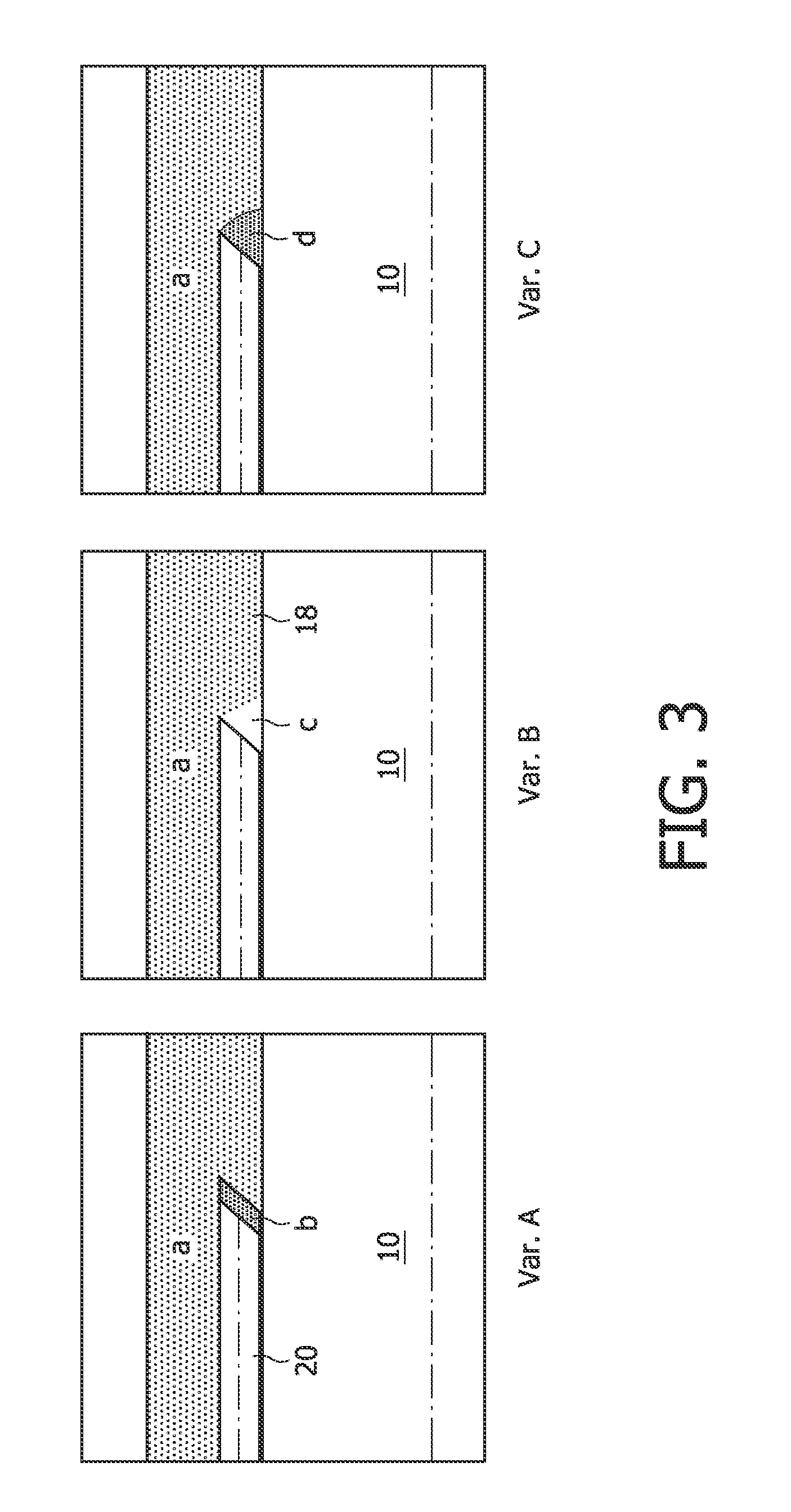
According to variant C of the first embodiment, shown in FIG. 3, first a curable droplet or layer, containing reflective particles (indicated with d), is provided, covering the inclined end of the fibre. In this way the inclined end of the fibre is covered with reflective particles leading to oblique outcoupling of light. Subsequently, a curable layer (a) which is fully transparent is applied to make the outer surface fully flat without sharp edges.
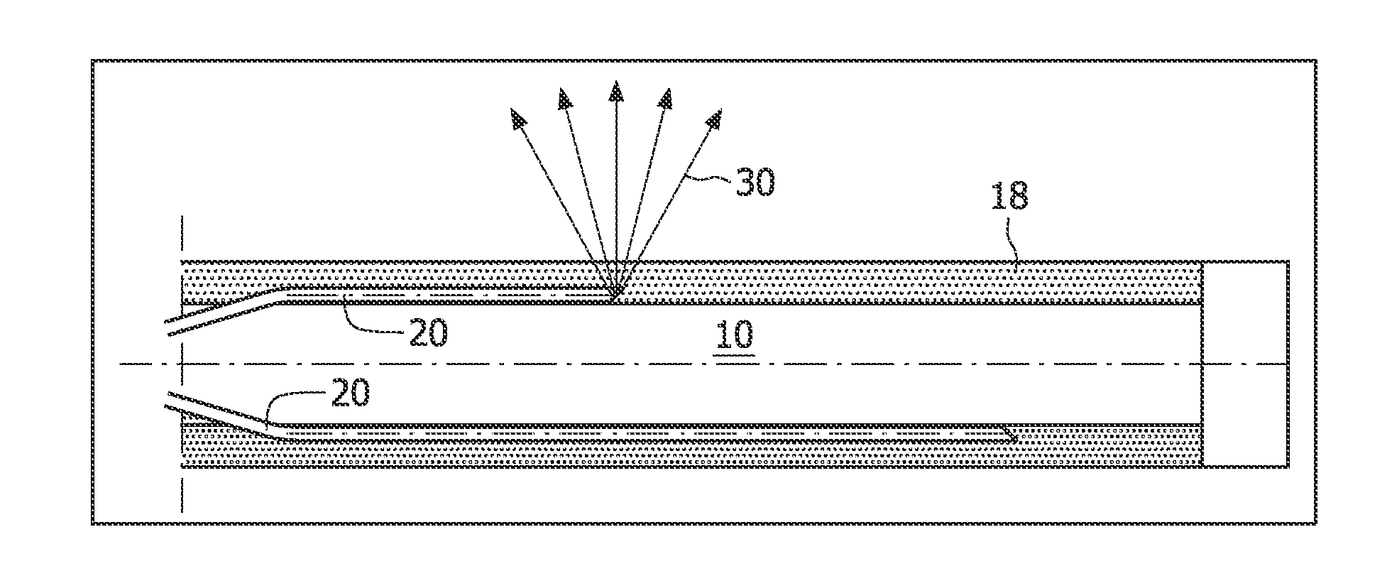
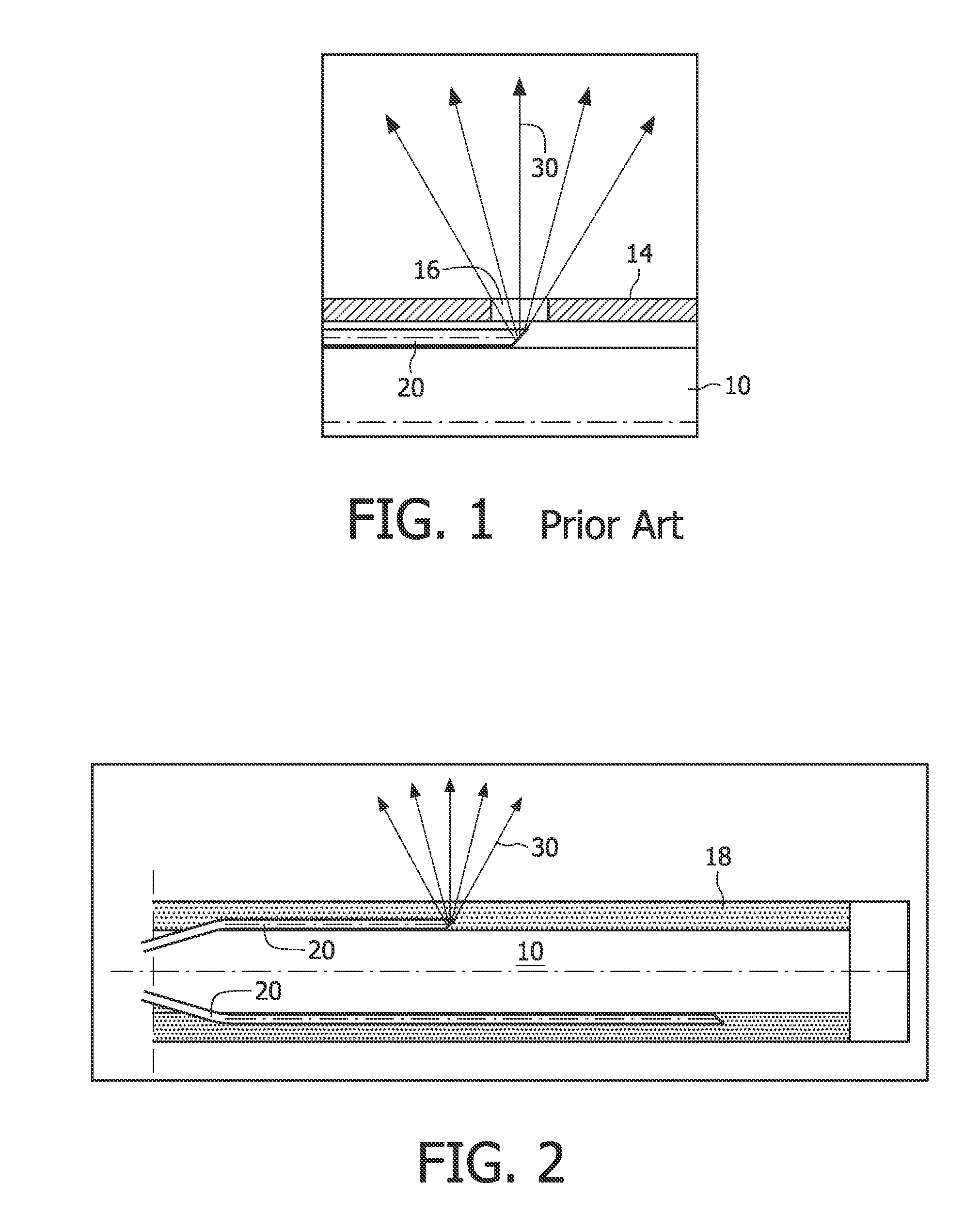
Since the wall of the shaft is fully transparent, it is, in principle, possible to emit the light from a tip of a fibre in any direction relative to the axis of the shaft. Thus, the light should be emitted from the tip of a respective fibre to a predefined direction, i.e. with a predefined angle, to make sure that a user of the device will know which tissue located around or inside the biopsy device, is inspected.
According to an exemplary embodiment, there is provided a plurality of fibres, each of which has a predefined inclination to th...
PUM
 Abstract
Description
Claims
Application Information