Left atrial appendage devices and methods

a technology of appendage and left atrial, which is applied in the field of appendage and methods for manipulating, positioning, clamping and stapling tissue, can solve the problems of reducing the heart's ability to properly function as a pump, increasing the risk of acquiring a number of potentially deadly complications, and affecting the quality of life, so as to prevent clots

Inactive Publication Date: 2011-01-13
ATRICURE
View PDF42 Cites 58 Cited by
  • Summary
  • Abstract
  • Description
  • Claims
  • Application Information

AI Technical Summary

Benefits of technology

[0011]In general, the present invention provides a device for manipulating and / or positioning tissue, such as clamping the left atrial appendage. Of particular interest is providing a device capable of bringing two tissue structures together. In one procedure, a clip applier may be used to apply one or more clips to the left atrial appendage of the heart to prevent clots from the left atrial appendage from embolizing and causing harm to the patient, such as a stroke. Clips are typically configured to segregate the left atrial appendage without severing the appendage, but otherwise any suitable configuration is contemplated. In one embodiment, clip applier may be used to simultaneously clip and excise the atrial appendage.
[0014]A further version of the invention includes a pair of flexible arms forming the end of one arm or plate of the clip to create the locking mechanism. The flexible arms fit within recesses in locking arms or posts extending from the opposing plate of the clip. To create a low profile a detent may be located in the flexible arms to allow the top of the locking arm to rest therein. One or more applier devices may be used to place and actuate the flexible arm clip. Projections on the applier may be set to engage openings in the flexible arms. Manipulation of the projections allows the flexible arms to be moved into the recesses to lock the clip in the closed position.
[0015]Yet a further version of the invention includes a cabled clip. This version has two plates and a cable. The cable extends from one end of the first plate, through a first cable opening in the first end of the second plate, through a second cable opening in the second end of the second plate, and through a third cable opening in the second end of the first plate. When the cable is pulled, it forces the plates into closer proximity, thereby clamping any tissue located therebetween. To hold the cable in place, teeth may extend from one or both sides of the cable. The teeth are configured to coordinate with one or more locking teeth in the third cable opening, thereby allowing the cable to move in only one direction through the opening. One or more applier devices may be used to place and actuate the cable clip. The applier device(s) may include a grip for holding the clip and a grip for holding the cable. While the clip is held, the cable is pulled. To prevent overcompression of the tissue a tension limiter may be used. The tension limiter may take the form of a weak point somewhere along the length of the cable, a limit on the amount of force a coordinating applier is capable of delivering, and / or a motion stop to prevent the cable motion or the plate motion. Other variations of the cable clip may use one or two worm gears on straight or inclined tracks to drive the motion of the cable.

Problems solved by technology

This rapid quivering reduces the heart's ability to properly function as a pump.
Atrial fibrillation typically increases the risk of acquiring a number of potentially deadly complications, including thrombo-embolic stroke, dilated cardiomyopathy and congestive heart failure.
Quality of life is also impaired by common AF symptoms such as palpitations, chest pain, dyspnea, fatigue and dizziness.
Studies have shown, however, that warfarin tends to be under-prescribed for AF.
Patient compliance with warfarin is problematic, and the drug requires vigilant blood monitoring to reduce the risk of bleeding complications.
For example, currently available devices can be difficult to position and secure on epicardial tissue to perform an ablation.
Ablation devices often have no means for shielding ablative energy, to avoid unwanted burning of tissues in the vicinity of the heart, such as the esophagus.
Relatively few devices can be secured to epicardial tissue with sufficient force to allow for stabilization of the heart.
And many ablation devices may not be introduced by minimally invasive means, thus requiring an open surgical procedure.

Method used


Image

  • Left atrial appendage devices and methods
  • Left atrial appendage devices and methods
  • Left atrial appendage devices and methods

Examples


Embodiment Construction

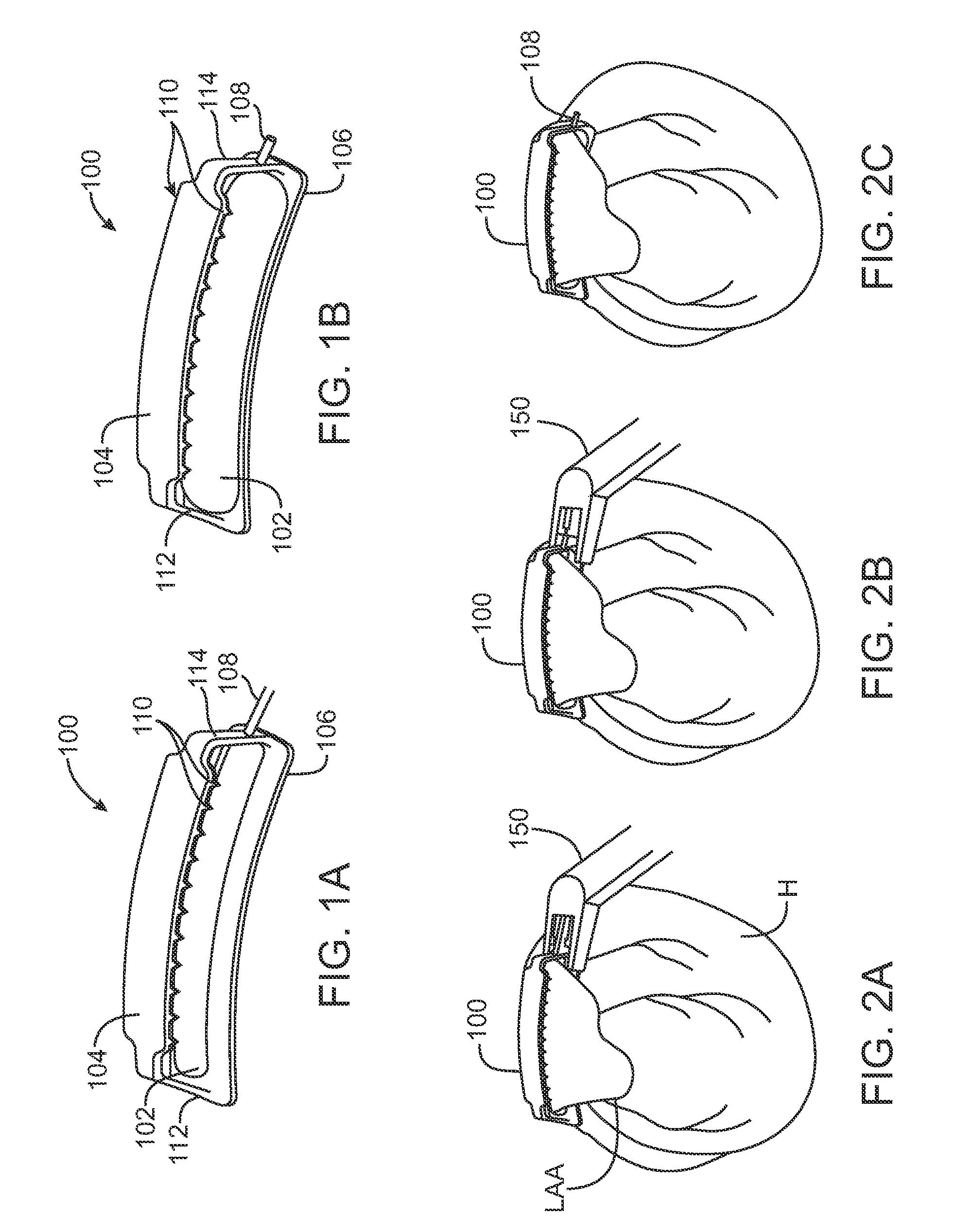
[0035]FIGS. 1A and 1B show perspective views of an inflatable clip 100 having a balloon 102 between the two plates 104, 106 forming the arms of the clip 100. FIG. 1A shows the inflatable clip 100 prior to inflation. In FIG. 1B, the balloon 102 has been inflated and the inflation tube 108 is has been crimped to provide permanent closure. In this embodiment, the top plate 104 of the inflatable clip 100 has one, two or more rows of traction tines or teeth 110 extending downward. The teeth 110 are located at or near the edge of the top plate 104 to allow the teeth 110 to puncture the left atrial appendage LAA on either side of the balloon 102 when the clip 100 is moved to the closed position. The balloon 102 is attached to the lower plate 106 of the inflatable clip 100. The balloon 102 extends along most or all of the length of the clip 100. The balloon 102 is sized and located such that as the balloon 102 inflates, the edges of the balloon 102 do not extend into the path of the teeth 1...


PUM


Abstract

Devices and methods for clamping tissue and / or moving two tissue structures together by moving two plates or arm together. The pressure or force applied to the tissue may be used to bring the tissue together, to seal an opening or to cut through and remove a portion of the tissue. In one procedure disclosed, a clip applier may be used to apply one or more clips to the left atrial appendage of the heart to prevent clots from the left atrial appendage from embolizing and causing harm to the patient, such as a stroke.

Description

CROSS-REFERENCES TO RELATED APPLICATIONS[0001]This application is a divisional of application Ser. No. 10 / 988,003 filed Nov. 12, 2004, which is a continuation-in-part of application Ser. No. 10 / 310,675 filed Dec. 4, 2002, which claims priority to U.S. Provisional Patent Application Ser. No. 60 / 337,070, filed Dec. 4, 2001. This application also claims priority of U.S. Provisional Patent Application Ser. No. 60 / 519,359, filed Nov. 11, 2003. The entire contents of the above applications are hereby incorporated by reference in their entirety.FIELD OF THE INVENTION[0002]The present invention pertains to apparatus and methods for manipulating, positioning, clamping and stapling tissue. In particular it is a clamping device, which is particularly useful for treating the left atrial appendage of the heart to treat atrial fibrillation, but may also be useful for treatment of other tissues including the stomach, in gastric or bariatric surgery, or the lungs.BACKGROUND OF THE INVENTION[0003]At...

Claims


Application Information

Patent Timeline
Patent Type & Authority Applications(United States)
IPC IPC(8): A61B18/20A61B17/08A61B17/10A61B18/18
CPCA61B17/122A61B17/1285A61B17/320016A61B17/083A61B17/068A61B17/08A61B2017/00243A61B17/0057
Inventor BERTOLERO, ARTHUR A.IBRAHIM, TAMERGEYSTER, STEVE
Owner ATRICURE
Why Eureka
Try Eureka