Bone fixation using an intramedullary pin

Inactive Publication Date: 2011-01-13
ORFALY ROBERT M
View PDF12 Cites 61 Cited by
  • Summary
  • Abstract
  • Description
  • Claims
  • Application Information

AI Technical Summary

Benefits of technology

[0009]The present disclosure provides a system, including methods, apparatus, and kits, for fixation of a bone, such as the clavicle, using an intramedullary pin. The pin may be threaded in a leading region of the pin and may define one or more transverse apertures in the trailing region of the pin to receive one or more fasteners. In so

Problems solved by technology

These include the typical degree of fracture displacement and comminution, the small diameter of the bone leading to small fracture surfaces, the poor periosteal blood supply resulting from the limited muscular attachments, the significant forces crossing the bone, and the difficulty in clinically achieving splinting to minimize fracture motion.
However, greater scrutiny has led to a shifting consensus that these injuries can lead to prolonged disability as one awaits fracture healing and that nonunions commonly remain painful, particularly with overhead use.
The most common reason for late operation in the surgically treated group was hardware irritation requiring removal.
Disadvantages of this mode of fixation include the common prominence of the lateral nut as

Method used


Image

  • Bone fixation using an intramedullary pin
  • Bone fixation using an intramedullary pin
  • Bone fixation using an intramedullary pin

Examples


example 1

Exemplary Pin with Optional Extension Member

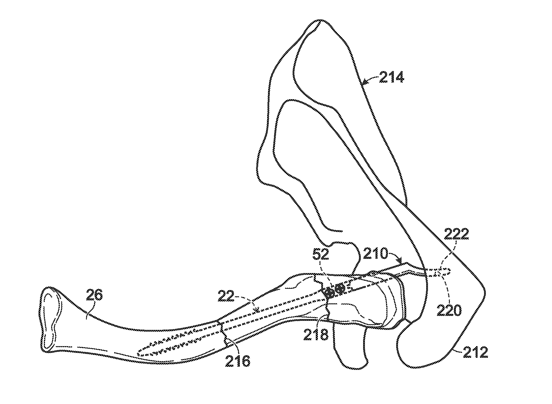
[0075]FIG. 17 shows a superior view of a multiply fractured clavicle 26 being fixed with pin 22, with the pin secured to an extension member 210. The extension member extends away from the pin to engage acromion 212 of a scapula 214 adjacent the clavicle. The extension member may be an optional attachment extending from the trailing end of the pin. Use of the extension member may be suitable when the pin is installed in a fractured clavicle that has multiple fractures 216, 218, with at least one of the fractures overlapping head 52 of the pin. Extension member 210, which may be termed a lateral or trailing flange or hook, may be bolted or otherwise attached to the head of the pin. In cases of distal or segmental clavicle fractures in which distal screw fixation may be insufficient, this attachment may be used. Extension member 210 may pass inferior to the mid-portion of the acromion and may or may not extend into the acromion. The extensio...

example 2

Selected Embodiments

[0076]This example describes selected embodiments of the present disclosure, presented without limitation as a series of numbered sentences.

[0077]1. A device for bone fixation, comprising: a pin configured to be placed longitudinally in a bone and including a wider head connected to a narrower shaft, the shaft having a thread formed thereon in a leading region of the pin to permit threaded engagement of the leading region with bone, and the head defining one or more transverse apertures to receive fasteners that attach a trailing region of the pin to bone.

[0078]2. The device of paragraph 1, wherein the pin tapers between the head and the shaft.

[0079]3. The device of paragraph 1, wherein the shaft includes a threaded portion having the thread formed thereon and a nonthreaded portion lacking the thread, and wherein the nonthreaded portion is disposed between the threaded portion and the head and is longer than the threaded portion.

[0080]4. The device of paragraph 1...


PUM


Abstract

System, including methods, apparatus, and kits, for fixation of a bone, such as the clavicle, using an intramedullary pin. The pin may be threaded in a leading region of the pin and may define one or more transverse apertures in the trailing region of the pin to receive one or more fasteners. In some embodiments, the system may include the pin and a jig for installation of the pin. The jig may include a sleeve that connects to the pin and is configured to be advanced toward the pin and against bone to compress the bone, to permit at least one fastener to be placed into a transverse aperture of the pin while the bone is compressed.

Description

CROSS-REFERENCE TO PRIORITY APPLICATION[0001]This application claims the benefit under 35 U.S.C. §119(e) of U.S. Provisional Patent Application Ser. No. 61 / 225,137, filed Jul. 13, 2009, which is incorporated herein by reference in its entirety for all purposes.INTRODUCTION[0002]The clavicle is an S-shaped bone, alternatively referred to as a collarbone, that represents the only direct skeletal connection between the arm and the chest wall. As such, the clavicle is critical to maintaining the appropriate position of the shoulder in relation to the chest and provides a mechanical strut across which muscles that motor the shoulder exert force. The clavicle is a subcutaneous bone, connecting the sternum and scapula, with a paucity of soft tissue attachments. The most important of these attachments is the confluence of the deltoid and trapezial muscular attachments, referred to as the deltotrapezial fascia.[0003]Fractures of the midportion of the clavicle (the “clavicular shaft”) are com...

Claims


Application Information

Patent Timeline
IPC IPC(8): A61B17/58
CPCA61B17/1717A61B17/1725A61B17/72A61B17/1739A61B17/7291A61B17/8872A61B17/7225
Inventor ORFALY, ROBERT M.
Owner ORFALY ROBERT M
Why Eureka
Try Eureka