Inter-Body Implantation System and Method

a technology of interbody and implantation, which is applied in the field of interbody implantation system and method, can solve the problems of inability to achieve repair, inability to perform surgery, and inability to accurately and quickly place, so as to improve recovery time for disc replacement surgery, reduce surgery time, and minimize the effect of surgery

Active Publication Date: 2011-01-13
R TREE INNOVATIONS
View PDF104 Cites 100 Cited by
  • Summary
  • Abstract
  • Description
  • Claims
  • Application Information

AI Technical Summary

Benefits of technology

[0012]The present invention obviates the aforementioned difficulties in the prior art by providing an improved inter-body device that more closely resembles natural disc physiology and by providing a system and method for deploying improved inter-body devices that enables a surgeon to accurately and quickly place an inter-body device of appropriate size in a disc space, thereby minimizing surgery times and greatly enhancing recovery times for disc replacement surgeries.

Problems solved by technology

However, developmental or genetic irregularities, trauma, chronic stress and degeneration due to wear may result in the need for surgical intervention to effect repair.
One of the major difficulties with many prior art discs is that they are most easily inserted utilizing an anterior surgical insertion due to the structure of the spine and arrangement of nerves proximate the spine.
The anterior surgical approach to disc replacement is, however, quite invasive.
Furthermore, many prior art disc replacements are complex devices made of a combination of materials and are also bulky and difficult to place properly between adjacent vertebrae.
However, these materials tend to be easily damaged during implantation and also tend to migrate into undesired areas of the body.
Implantation of these prior art devices is typically quite unwieldy and invasive due primarily to their complex structure and the complex geometry of the human spine.

Method used


Image

  • Inter-Body Implantation System and Method
  • Inter-Body Implantation System and Method
  • Inter-Body Implantation System and Method

Examples


Embodiment Construction

)

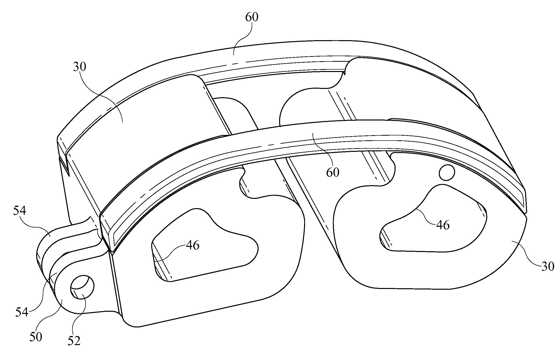
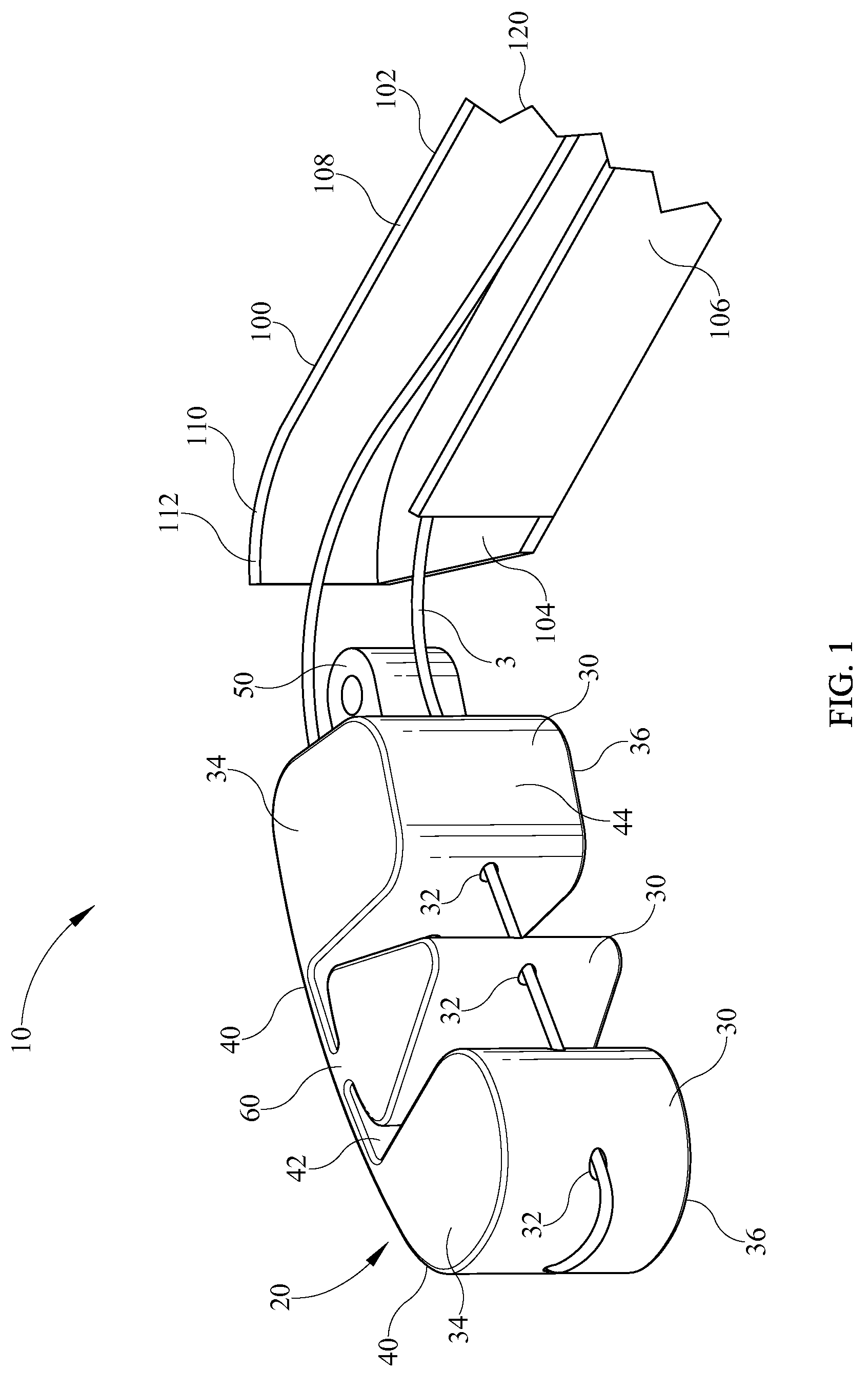
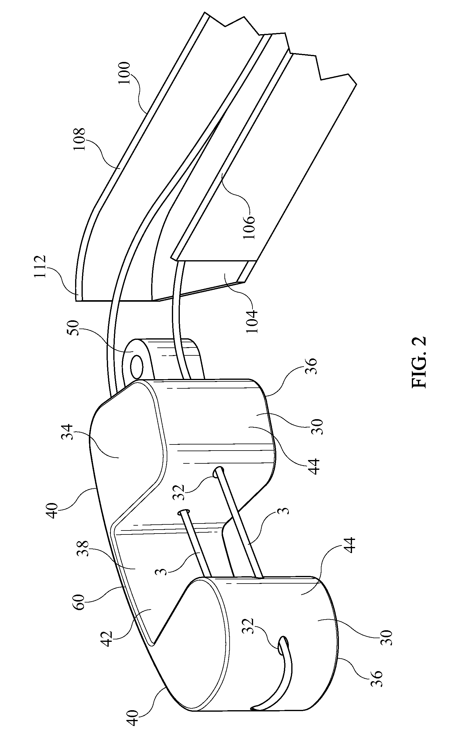
[0099]Referring now to the drawing Figures, and in particular FIGS. 1-3, and in accordance with a preferred constructed embodiment of the system 10 of the present invention, there is depicted an inter-body device 20 and an inserter tube 100 for orienting and inserting said inter-body device 20 into a disc space of a human spine. Drawing FIGS. 50 and 55 depict one example of the insertion of inter-body device 20 into a disc space 2 of a spine 1 between vertebrae 4, and may be referred to throughout this specification for reference to the human anatomy to which the present invention is applied. Furthermore, it should be noted that the disc to be replaced by the inter-body device 20 of the present invention is first removed by a surgeon performing a thorough discectomy. Typically, it is desirable to extend the discectomy to a contralateral half of the disc space to allow placement of the longest inter-body device 20 possible and to maximize bony surface exposure for fusion to occur. I...


PUM


Abstract

A system for implanting an inter-body device between adjacent vertebrae comprises an inter-body device having a plurality of cans secured to a flexible bridge and having a relief portion therebetween. An inserter tube and complementary bullnoses are advantageously secured to the vertebrae by an extension arm for securing the assembly precisely in place. A plurality of articulating trial implants are provided to test fit a disc space for the proper sized inter-body device.

Description

CROSS-REFERENCE TO RELATED APPLICATIONS[0001]This application claims the benefit of co pending U.S. Provisional Patent Application Ser. No. 61 / 224,333 filed Jul. 9, 2009 and entitled “Improved Inter-Body Implantation System and Method”.BACKGROUND OF THE INVENTION[0002]1. Field of the Invention[0003]The present invention relates generally to an inter-body device for intervertebral disc replacement or inter-body spinal fusion and more specifically to a system including a device for disc replacement or an inter-body device for spinal fusion and an insertion system and method for placing the aforementioned devices in an intervertebral space utilizing a plurality of surgical approaches.[0004]2. Description of the Related Art[0005]The normal human spine is comprised of seven cervical, twelve thoracic, and five lumbar vertebrae. Intervertebral discs are interposed between adjacent vertebrae with the exception of the first two cervical vertebrae. The spinal vertebrae are supported by ligame...

Claims


Application Information

Patent Timeline
Patent Type & Authority Applications(United States)
IPC IPC(8): A61F2/44A61B17/58
CPCA61B17/1757A61F2310/00023A61F2/4465A61F2/4611A61F2/4684A61F2002/2835A61F2002/30056A61F2002/3008A61F2002/30092A61F2002/30133A61F2002/30365A61F2002/30462A61F2002/30492A61F2002/30504A61F2002/30538A61F2002/30571A61F2002/30579A61F2002/30596A61F2002/30598A61F2002/30626A61F2002/30632A61F2002/30637A61F2002/30672A61F2002/30808A61F2002/30879A61F2002/30892A61F2002/4415A61F2002/448A61F2002/4627A61F2002/4629A61F2002/4679A61F2210/0014A61F2220/0025A61F2220/0033A61F2220/0075A61F2230/0015A61F2250/0006A61F2250/0032A61F2250/0098A61B17/708A61F2/46A61F2002/305A61F2002/30594A61F2002/30624
Inventor PUNO, ROLANDO M.
Owner R TREE INNOVATIONS
Why Eureka
Try Eureka