Elements of a femoral prosthesis with a modular neck, tooling for implanting a femoral prosthesis and method of implantation

a femoral prosthesis and modular technology, applied in the field of femoral prosthesis, can solve the problems of inability to transpose and inability to achieve the effect of implantation

Inactive Publication Date: 2011-01-13
CERAM CONCEPT L L C
View PDF8 Cites 27 Cited by
  • Summary
  • Abstract
  • Description
  • Claims
  • Application Information

AI Technical Summary

Benefits of technology

[0007]The invention aims to remedy the disadvantages of the prior art and in particular to provide means to prevent any sinking into the medullary cavity of the spindle of a prosthesis with a modular neck, in particular when no cements are used.
[0011]Due to its positioning on the rod set back from the tenon, the tongue will not be in contact with the bone or with the femoral prosthetic implant when the tenon is inserted into the cavity of the prosthetic implant acting as a mortise. The tongue will therefore not hinder the fitting of the tenon into the cavity. If the femoral implant sinks into the medullary cavity, the part of the tongue protruding radially beyond the tenon comes into abutment with the bone to prevent it from further sinking.

Problems solved by technology

Such an arrangement cannot be transposed as such to prostheses with a modular neck since, from a mechanical point of view, it is not possible to achieve simultaneously without cement the fixing of the neck to the femoral prosthetic implant and the coming into abutment of the tongue against the femoral section.

Method used


Image

  • Elements of a femoral prosthesis with a modular neck, tooling for implanting a femoral prosthesis and method of implantation
  • Elements of a femoral prosthesis with a modular neck, tooling for implanting a femoral prosthesis and method of implantation
  • Elements of a femoral prosthesis with a modular neck, tooling for implanting a femoral prosthesis and method of implantation

Examples


Embodiment Construction

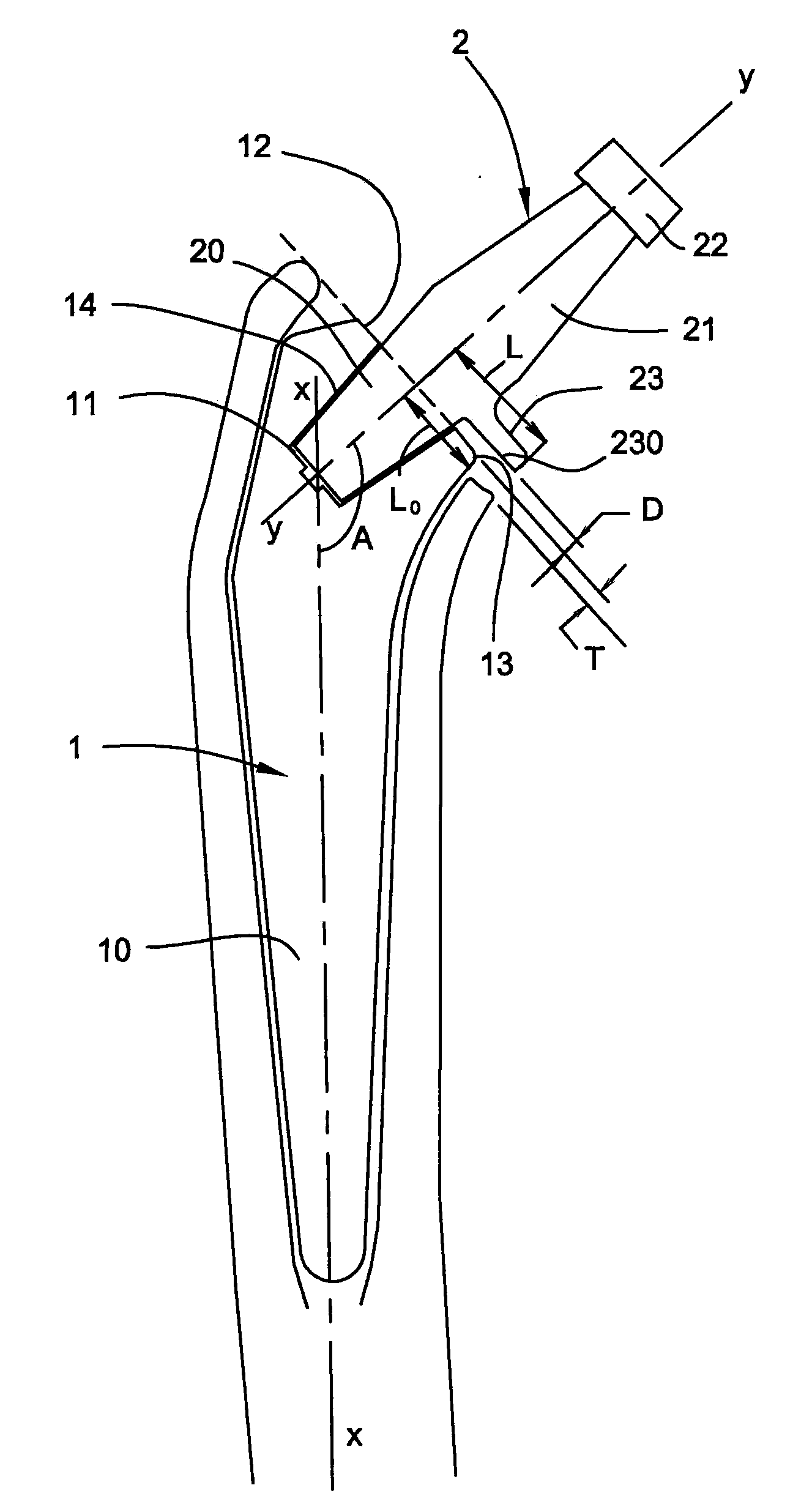
[0048]With reference to FIG. 1, the diaphysis of a femur has been separated from the femoral neck by sectioning using an oscillating saw along a bone section plane P, then the diaphyseal cavity was partially hollowed out and scraped using a scraper in order to introduce therein a prosthetic implant 1. The implant 1 has a diaphyseal part 10 of tapered shape along a longitudinal axis X-X which, during the implantation, becomes coincident with the femoral diaphyseal axis. The implant 10 widens in its metaphyseal upper part 11 and has a flat face 12 delimited by an outer edge 13 and in which there is formed a frustoconical cavity 14 defining an axis Y-Y, this axis being perpendicular to the flat face 12 and close to the diaphyseal axis of the head of the femur before sectioning.

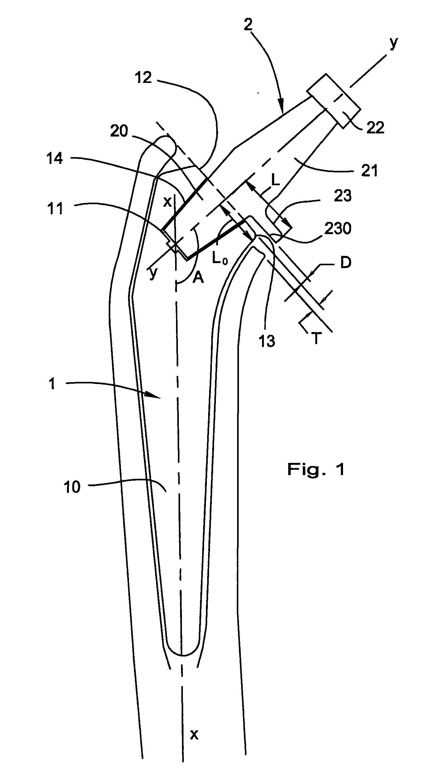
[0049]Into the frustoconical cavity 14 of the femoral prosthetic implant there has been fitted a correspondingly shaped tenon or cone 20 which constitutes the lower part of a modular neck 2 that provided with a p...


PUM


Abstract

A modular assembly for a femoral prosthesis comprises a femoral prosthetic implant forming a spindle of elongate and tapered shape and a one-piece neck. The implant consists of a diaphyseal lower part and a metaphyseal upper part having a flat face delimited by an outer edge and in which a cavity is formed. The neck is formed of a tenon having a shape corresponding to the cavity, said tenon being fitted into the cavity along an insertion axis YY perpendicular to the flat face and a rod provided with an interface for fixing a cup that is to be inserted into the acetabulum of the hip bone. The rod is provided with a tongue which protrudes parallel to the flat face in a radial direction with respect to the insertion axis and directed towards the interior of the obtuse salient angle, at a distance from the flat face of between 0.3 mm and 1.5 mm measured along the insertion axis, the tongue having a free end located at a greater distance from the insertion axis than the part of the edge located opposite the tongue. The free end of the tongue overhangs somewhat with respect to the outer edge of the flat face of the femoral prosthetic implant, in such a way as to ensure that, in the event of sinking of the implant into the medullar cavity, the tongue will come into abutment against the femoral calcar.

Description

TECHNICAL FIELD OF THE INVENTION[0001]The invention relates to the field of femoral prostheses to be implanted in the human body.BACKGROUND OF THE INVENTION[0002]As is well-known in the art, a hip prosthesis usually comprises a femoral prosthetic implant intended to be introduced into the medullary cavity of the femur and a neck designed to receive, directly or otherwise, a cup intended to cooperate with the acetabulum of the hip bone.[0003]Essentially three types of prosthesis are known, namely a one-piece type in which the neck and the prosthetic head are integral with the femoral prosthetic implant, a two-piece type having wherein the neck is integral with the femoral prosthetic implant and cooperates with a modular head, and a three-piece type wherein each of the femoral prosthetic implant, neck and prosthetic head is modular. This latter modular design makes it possible to choose, during the implantation operation and according to the anatomy of the patient, firstly the femoral...

Claims


Application Information

Patent Timeline
Patent Type & Authority Applications(United States)
IPC IPC(8): A61F2/32A61B17/58
CPCA61B17/1637A61B17/1668A61F2/36A61F2/3609A61F2220/0033A61F2002/30332A61F2002/30334A61F2002/3631A61F2002/3652A61F2/4607
Inventor CRUCHET, PATRICK
Owner CERAM CONCEPT L L C
Why Eureka
Try Eureka