Junction box for solar modules

Inactive Publication Date: 2011-01-20
FPE FISCHER GMBH
View PDF7 Cites 19 Cited by
  • Summary
  • Abstract
  • Description
  • Claims
  • Application Information

AI Technical Summary

Benefits of technology

[0014]The objective of the present invention is to produce a junction box which guarantees

Problems solved by technology

Furthermore, with this structural arrangement of component chambers, the housing body, which is usually mounted on the rear side of t

Method used


Image

  • Junction box for solar modules
  • Junction box for solar modules
  • Junction box for solar modules

Examples


Example

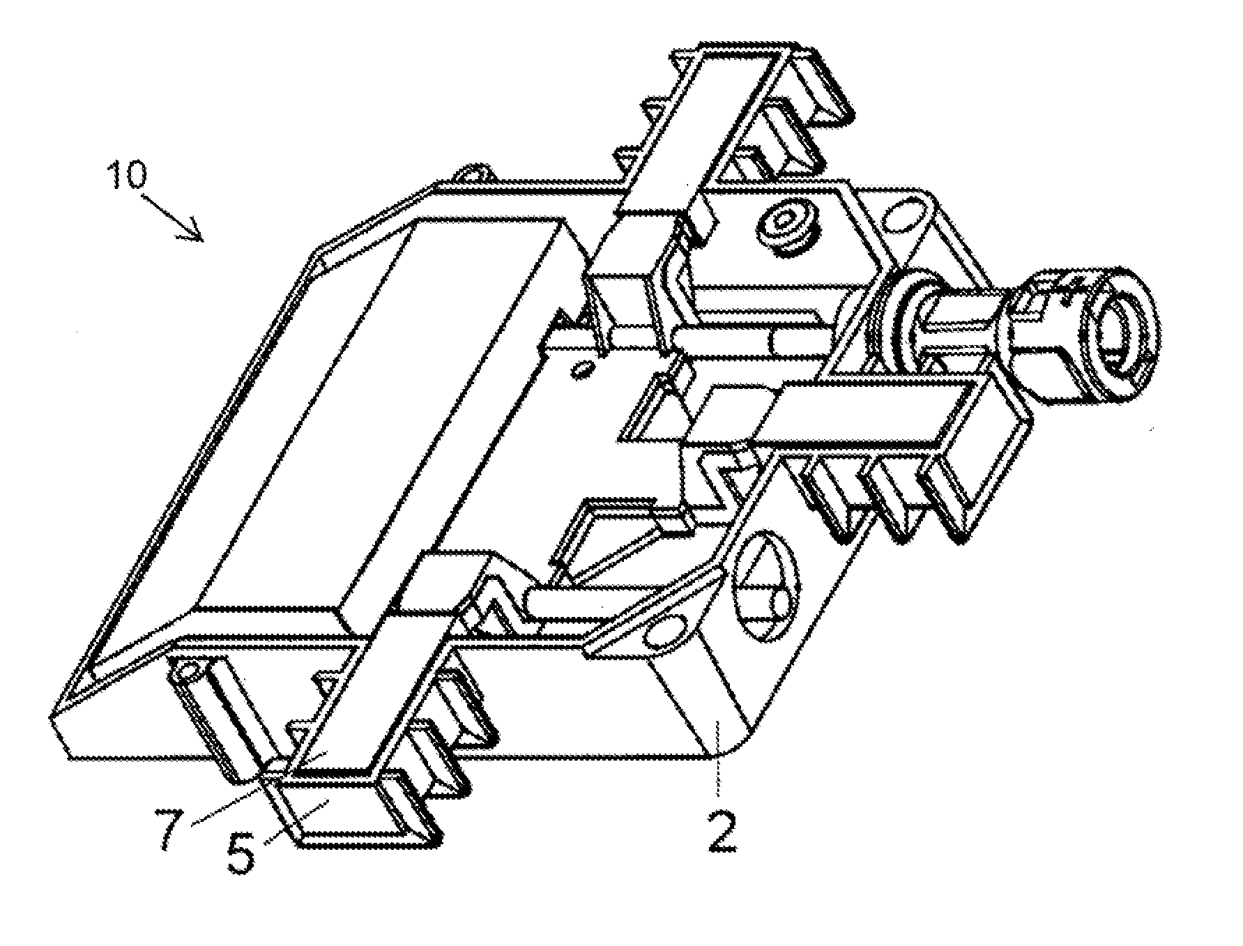
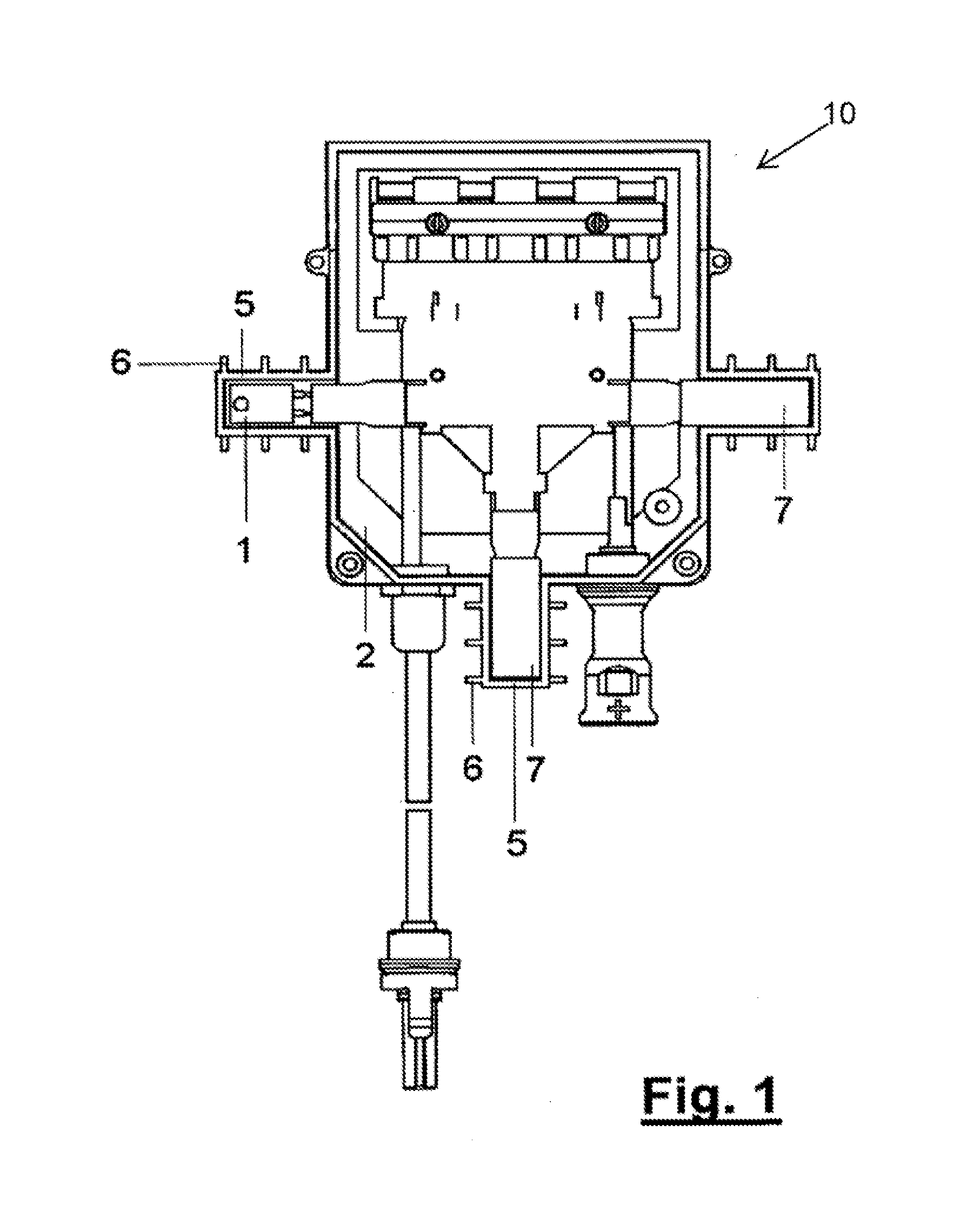
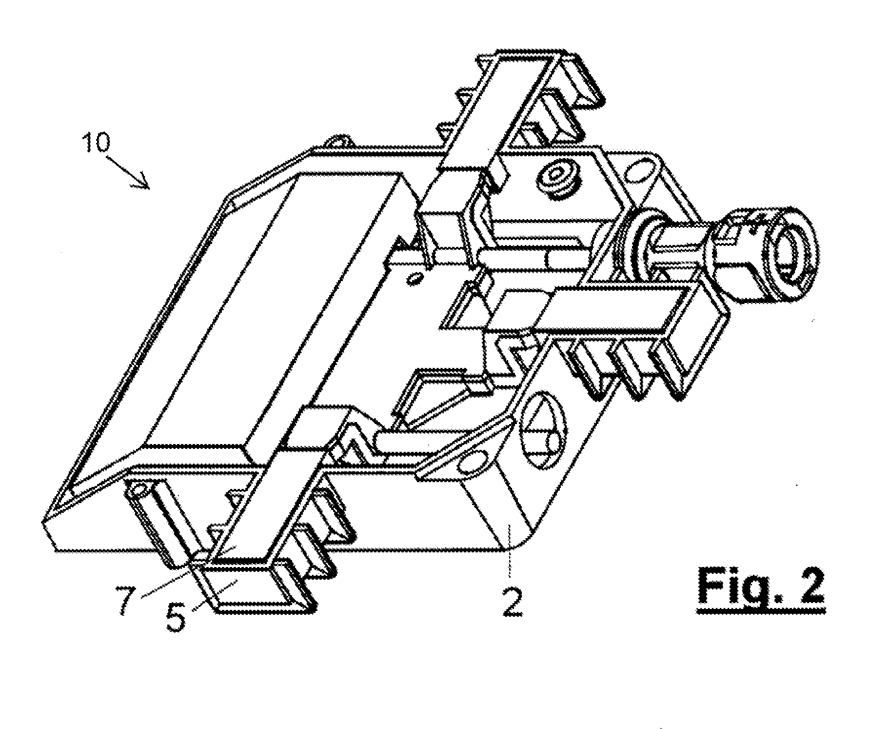
[0026]FIGS. 1-3 illustrate a junction box 10 according to the invention. The junction box comprises a die-cast aluminum housing body 2, a housing cover 3, and at least one component chamber 5 for retaining a component. In the embodiment shown, three component chambers 4 are provided on the side walls of the housing body 2. This illustration is by way of example only and is not intended to be limiting. As shown, the component chamber 5 projects distally outward from the sidewall in the manner of a balcony. An electrical component 1, for example, a bypass diode, that is to be assembled in a component chamber 5 is sheathed in an insulation covering 7 and inserted into the chamber 5 so as to be in firm contact with the inner walls of the chamber 5 and with the housing cover 3. A suitable insulation material for the covering 7 is thermally conductive silicone rubber, because of its heat dissipation and cushioning properties. The component chamber 5 has cooling fins 6, to facilitate heat ...


PUM


Abstract

The invention relates to a junction box which safely dissipates heat produced by electrical/electronic components assembled in the box. The junction box has a housing with cover and at least one component chamber that juts out from a side wall of the housing. The component chamber has cooling fins. An electric or electronic component, sheathed in insulation, is inserted into the component chamber, such that it fits firmly against the walls of the chamber. The cover has cooling fins and overhangs the body of the housing and the component chamber in several areas. The construction of the junction box with the component chambers that jut out from the body and the housing cover with overhang enhance heat dissipation and allow the box to be used with solar modules in which bypass flows up to 16 A and greater occur.

Description

BACKGROUND INFORMATION[0001]1. Field of the Invention[0002]The invention relates to a junction box which reliably dissipates the heat produced in the bypass diodes, MOSFETs or corresponding power semiconductors of a solar module.[0003]2. Description of the Prior Art[0004]During the operation of a solar installation, it is never possible to wholly exclude the shading of individual solar cells, for example due to clouds or falling leaves. Without protective measures, the so-called Zener effect would produce high power loss in the shaded solar cell, leading to a hot spot in this cell and, thus, almost always to destruction of the particular cell.[0005]For this reason, electronic components such as bypass diodes, MOSFETs, or comparable power semiconductors are typically connected in parallel to the solar cells or rows of series-connected solar cells. When shaded, the particular shaded cell or row of cells is thus bridged by the electronic component, thereby ensuring that the current pro...

Claims


Application Information

Patent Timeline
IPC IPC(8): H05K7/20
CPCH05K7/20409H05K7/20445H02S40/345H05K7/20854H02S40/34H05K7/2049Y02E10/50
Inventor PFEFFER, ROLAND
Owner FPE FISCHER GMBH
Why Eureka
Try Eureka