Method of manufacturing hollow microneedle structures

Active Publication Date: 2011-01-20
ELECTRONICS & TELECOMM RES INST
View PDF6 Cites 15 Cited by
  • Summary
  • Abstract
  • Description
  • Claims
  • Application Information

AI Technical Summary

Benefits of technology

[0025]The method may further include chemically treating t

Problems solved by technology

However, conventional needles used to collect biomaterials, such as blood, are practically problematic because they may cause pain during use and inflict external injuries.
However, this technique requires an additional etching process to provide a hollow needle sha

Method used


Image

  • Method of manufacturing hollow microneedle structures
  • Method of manufacturing hollow microneedle structures
  • Method of manufacturing hollow microneedle structures

Examples


Embodiment Construction

[0033]The present invention will be described more fully hereinafter with reference to the accompanying drawings, in which exemplary embodiments of the invention are shown. This invention may, however, be embodied in many different forms and should not be construed as being limited to the embodiments set forth herein. Rather, these embodiments are provided so that this disclosure is thorough and complete and fully conveys the concept of the invention to those skilled in the art. In the drawings, portions irrelevant to a description of the invention are omitted for brevity, and like numbers refer to like elements throughout.

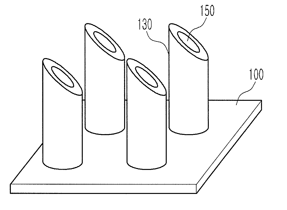
[0034]Hereinafter, a microneedle structure according to an exemplary embodiment of the present invention will be described with reference to FIG. 1.

[0035]Referring to FIG. 1, a microneedle structure manufactured according to an exemplary embodiment of the present invention may include a plurality of cylindrical microneedles 130. Each of the cylindrical microneedle...


PUM

PropertyMeasurementUnit
Angleaaaaaaaaaa
Diameteraaaaaaaaaa
Diameteraaaaaaaaaa

Abstract

Provided is a method of manufacturing a hollow microneedle structure. The method includes forming an injection mold having a through hole, filling the injection mold with a photoresist formed of a viscous material, and extruding the photoresist from the injection mold through the through hole, solidifying the extruded photoresist to form a needle-type photoresist structure, forming a seed layer on the surface of the photoresist structure, forming a metal plated layer on the seed layer, inclining an end tip of the photoresist structure having the metal plated layer, and removing the photoresist from the metal plated layer to form a hollow. Thus, the hollow microneedle structure can be manufactured to have such diameter, length, hardness, and inclination angle as to minimize pain. The hollow microneedle structure can be combined with an apparatus for detecting a biomaterial or injecting cosmetic substances or medicines, and variously applied.

Description

CROSS-REFERENCE TO RELATED APPLICATION[0001]This application claims priority to and the benefit of Korean Patent Application No. 10-2009-0065324, filed Jul. 17, 2009, the disclosure of which is incorporated herein by reference in its entirety.BACKGROUND[0002]1. Field of the Invention[0003]The present invention relates to a method of manufacturing microneedles, and more specifically, to a method of manufacturing hollow microneedles having inclined end tips.[0004]2. Discussion of Related Art[0005]In the field of bio-microelectromechanical systems (bio-MEMS) technology, samples may need to be pretreated in order to enable early detection and chemical analysis for diseases on small chips. This requires collecting blood while minimizing pain. Accordingly, an essential component called a microneedle is required.[0006]In general, needles are variously utilized in hospitals. For example, the needles are used to collect biomaterials, such as blood, in order to detect diseases, inject drugs i...

Claims


Application Information

Patent Timeline
IPC IPC(8): B44C1/22
CPCA61M37/0015A61M2037/0023A61M2037/003A61M2037/0046B81C1/00111B29C33/3842B29L2031/7544B29L2031/756B81B2201/055A61M2037/0053A61M5/178A61M5/32
Inventor LEE, DAE SIKSONG, HYUN WOOJUNG, MOON YOUNPARK, SEON HEE
Owner ELECTRONICS & TELECOMM RES INST
Why Eureka
Try Eureka