Condenser microphone

Inactive Publication Date: 2011-01-20
AUDIO-TECHNICA
View PDF10 Cites 13 Cited by
  • Summary
  • Abstract
  • Description
  • Claims
  • Application Information

AI Technical Summary

Benefits of technology

[0020]When the battery cover is slid to the connector sleeve side to open the battery holder, one end of the conductive member increases in diameter and engages with the

Problems solved by technology

However, the battery built-in type condenser microphone has a movable part, the battery cover, as described above, and the grounding thereof is difficult to do, so that a high-frequency current caused by external electromagnetic waves (especially, strong electromagnetic waves emitted from a cellular phone) intrudes into the microphone housing through a contacting part of the movable part and a fixed part, whereby the high-frequency current is detected by the FET, and noise is generated easily.
However, in this method, since the contacting part is a point contact, a sufficient effect cannot sometimes be achieved in inhibiting the high-frequency and high-output electromagnetic waves emitted from the cel

Method used


Image

  • Condenser microphone
  • Condenser microphone
  • Condenser microphone

Examples


Embodiment Construction

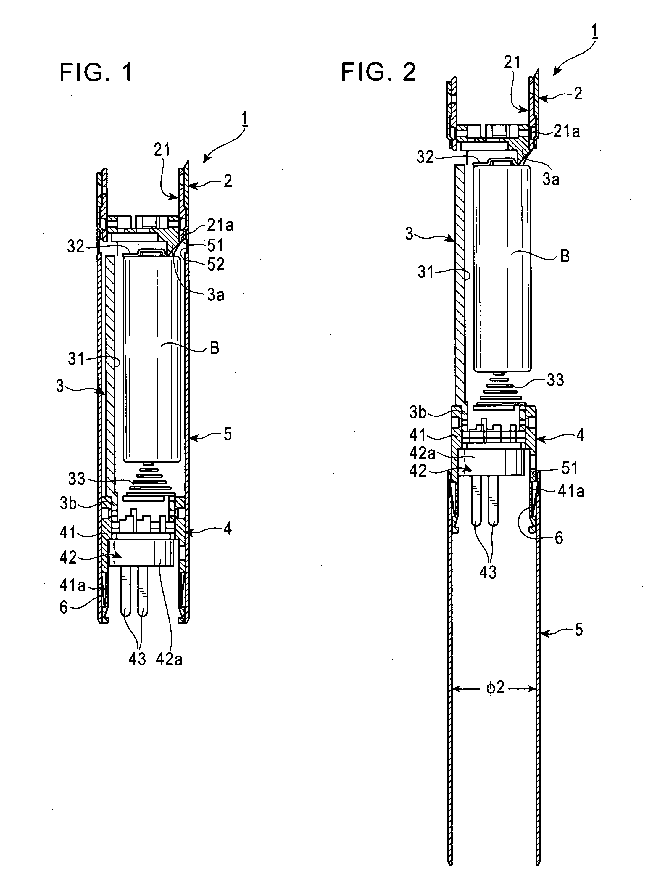
[0025]An embodiment of the present invention will now be described with reference to FIGS. 1 to 3. The present invention is not limited to this embodiment.

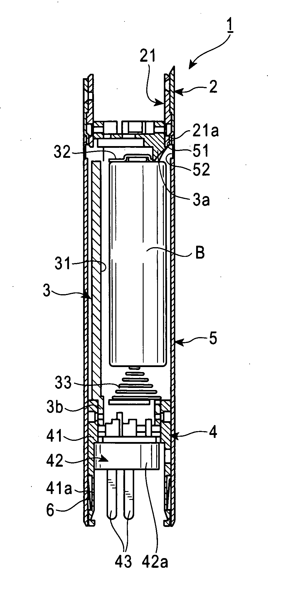
[0026]As shown in FIGS. 1 and 2, for a condenser microphone 1, a battery holder 3 is provided between a microphone housing 2 and an output connector 4, and is provided with an openable / closable battery cover 5.

[0027]Although FIGS. 1 and 2 show only the rear end part of the microphone housing 2, the microphone housing 2 is formed in a cylindrical shape by using a metallic material such as a brass alloy. In the interior thereof or on the front end side thereof, a condenser microphone unit (not shown) is mounted.

[0028]The battery holder 3 is made of a synthetic resin, and is provided with a ship's bottom shaped battery accommodating part 31 for accommodating a rod-like battery B such as an AA size battery. On the anode end part 3a side of the battery holder 3, an anode contact 32 consisting of a plate spring is provided, and on the c...


PUM


Abstract

In a condenser microphone having a battery holder and a battery cover therefor, one part is used as a member for grounding the battery cover and as a member for preventing the battery cover from coming off. In a condenser microphone 1 including a microphone housing 2 formed of a metallic cylindrical body; an output connector 4 provided with a predetermined number of terminal pins 43 in a metallic connector sleeve 41; a battery holder 3 provided between the microphone housing 2 and the output connector 4; and a battery cover 5 formed of a metallic cylindrical body for opening/closing the battery holder 3 by sliding, a first ring-shaped groove 41a is formed in the outer peripheral surface of the connector sleeve 41; in the first ring-shaped groove 41a, there is disposed a conductive member 6 consisting of a circular conical tube body in which one end thereof on the battery holder 3 side is in elastic contact with the inner peripheral surface of the battery cover 5, and the other end thereof on the opposite side has a diameter approximately equal to the diameter of the groove bottom of the first ring-shaped groove 41a; and in the inner peripheral surface of the battery cover 5, there is formed a second ring-shaped groove 52 with which the one end of the conductive member 6 increases in diameter and engages.

Description

CROSS-REFERENCE TO RELATED APPLICATION[0001]The present application is based on, and claims priority from, Japanese Application Serial Number JP2009-165476, filed Jul. 14, 2009, the disclosure of which is hereby incorporated by reference herein in its entirety.TECHNICAL FIELD[0002]The present invention relates to a condenser microphone. More particularly, it relates to a shield structure in a condenser microphone incorporating a driving battery.BACKGROUND ART[0003]A condenser microphone is provided with a condenser microphone unit (an electrostatic acoustic-electric converter) including a diaphragm and a backplate disposed opposedly, and the output impedance of the condenser microphone unit is very high. Therefore, the condenser microphone unit incorporates an impedance converter for converting impedance to low one. In many cases, as the impedance converter, a field effect transistor (FET) has been used.[0004]Usually, the condenser microphone is used by being connected to a phantom ...

Claims


Application Information

Patent Timeline
IPC IPC(8): H04R9/08
CPCH04R9/08
Inventor AKINO, HIROSHI
Owner AUDIO-TECHNICA
Why Eureka
Try Eureka