Supercharge Your Innovation With Domain-Expert AI Agents!

Grooved cmp polishing pad

a technology of polishing pad and groove, applied in the field of chemical mechanical polishing of substrates, can solve problems such as affecting the uniformity of polishing rate, and achieve the effect of improving the uniformity of polishing removal ra

Inactive Publication Date: 2011-01-20
CABOT MICROELECTRONICS CORP
View PDF7 Cites 15 Cited by
  • Summary
  • Abstract
  • Description
  • Claims
  • Application Information

AI Technical Summary

Benefits of technology

[0011]The polishing pads of the present invention provide an unexpected improvement in polishing removal rate uniformity over extended use (e.g., polishing of up to 650 semiconductor wafers) compared to a conventional grooved pad of similar construction, but with WL / WG equal to about 7.

Problems solved by technology

One problem in CMP relates to polishing slurry distribution over the polishing pad.
Ineffective distribution of the slurry across the surface of the polishing pad can lead to diminished polishing efficiency.

Method used


Image

  • Grooved cmp polishing pad
  • Grooved cmp polishing pad
  • Grooved cmp polishing pad

Examples


example 1

[0030]This example illustrates the superior removal rate stability and removal uniformity stability obtainable in copper CMP utilizing a polishing pad of the present invention.

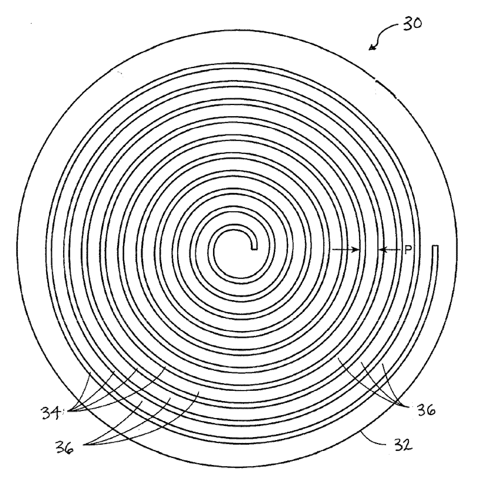
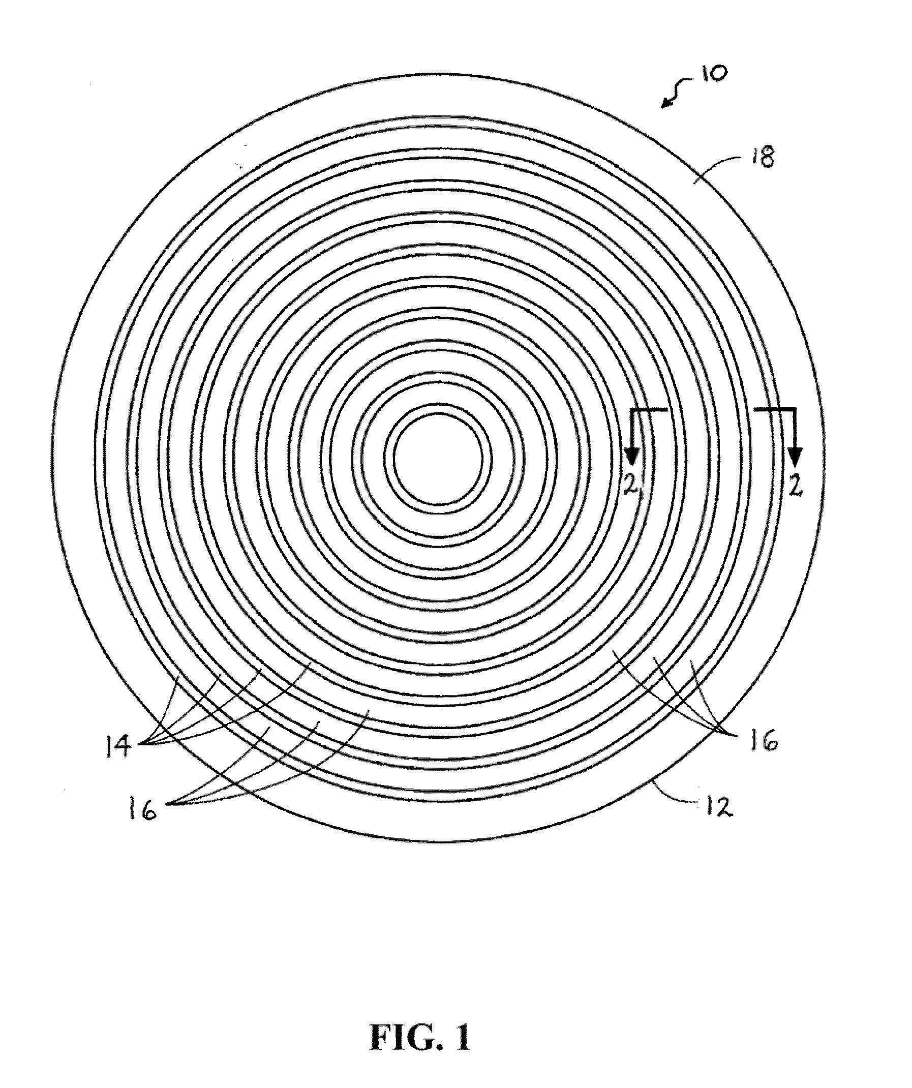
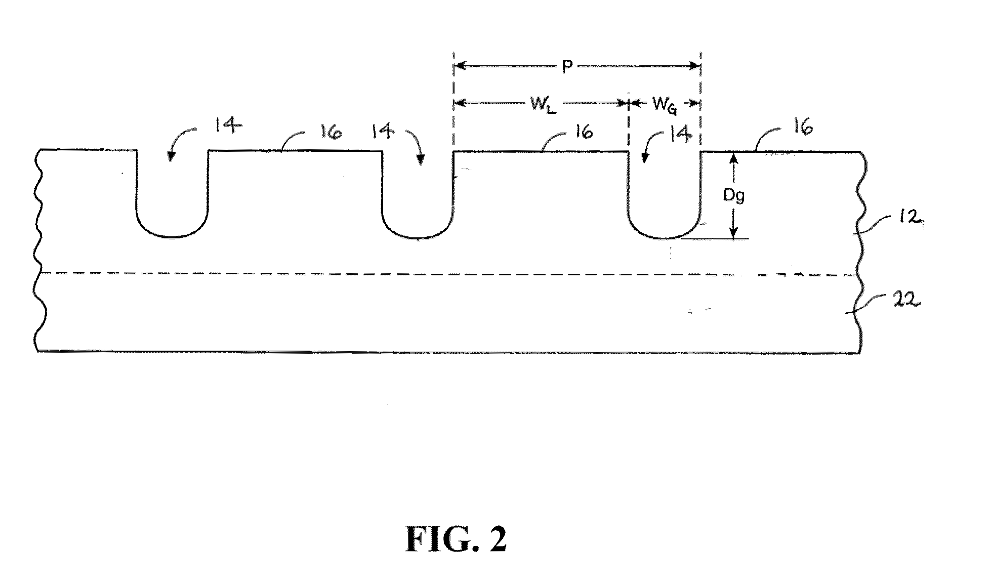
[0031]A polishing pad comprising a thermoplastic polyurethane surface layer including a series of concentric circular grooves each having a width, WG, of about 30 mil, separated by concentric landing surfaces having a width, WL, of 30 mil (pitch of 60 mil), with WL / WG equal to about 1. The polishing was repeatedly performed with the same pad on copper blanket wafers using the commercial polishing slurry C8800 (Cabot Microelectronics Corporation, Aurora, Ill.) on Mirra polisher under the following polishing conditions: down-force of 1 pounds-per-square inch (psi), platen speed of 93 revolutions-per-minute (rpm), carrier speed of 87 rpm, and a slurry feed rate of 100 milliliters-per-minute (mL / min). For comparison, copper blanket wafers were also polished under the same conditions with a similar polyurethane pol...

example 2

[0034]This example illustrates the effect of the grooving configuration on pad wear rate.

[0035]Three polishing pads of the invention comprising a thermoplastic polyurethane surface layer including a series of concentric circular grooves were used for relative pad wear test. The test was performed on an IPEC polisher with 7 ft-lb conditioning down force, 105 rpm platen speed, and 100 rpm conditioner rotational speed. Conditioner was from 3M Co (Model A188). D.I. water was used and the test last for 40 minutes. Wear rate was calculated using data from minute 10 to minute 40, and normalized to mil-per-hour by times 2. The pads had the following dimensions: Pad 60 / 20−WG=20 mil, WL=40 mil, pitch=60 mil, WL / WG=2; Pad 60 / 30−WG=30 mil, WL=30 mil, pitch=60 mil, WL / WG=1; and Pad 40 / 20−WG=20 mil, WL=20 mil, pitch=40 mil, WL / WG=1. For comparison, a similar polyurethane polishing pad having concentric annular grooves separated by concentric annular landing surfaces, but having WL of about 70 mil...


PUM


Abstract

The present invention provides polishing pads for use in CMP processes. In one embodiment, a pad comprises a surface defining a plurality of grooves with landing surfaces separating the grooves, the landing surfaces together defining a substantially coplanar polishing surface, each groove having a depth of at least about 10 mil and a width, WG, with any two adjacent grooves being separated from each other a landing surface having a width, WL, wherein the quotient WL / WG is less than or equal to 3. In a preferred embodiment, the surface of the pad defines a series of concentric substantially circular grooves. In an alternative embodiment, the surface of the pad defines a spiral groove having a depth of at least about 10 mil and a width WG, and a spiral landing surface outlining spiral groove the having a width, WL, wherein the spiral landing surface defines a substantially coplanar polishing surface and the quotient WL / WG is less than or equal to 3.

Description

CROSS-REFERENCE TO RELATED APPLICATIONS[0001]This application claims the benefit of U.S. Provisional Application for Patent Ser. No. 61 / 271,068, filed on Jul. 16, 2009, which is incorporated herein by reference.FIELD OF THE INVENTION[0002]The present invention relates generally to chemical mechanical polishing of substrates, and more particularly to a polishing pad having a grooved pattern for a chemical mechanical polishing system.BACKGROUND OF THE INVENTION[0003]Compositions and methods for chemical-mechanical polishing of the surface of a substrate are well known in the art. Polishing compositions (also known as polishing slurries, CMP slurries, and CMP compositions) for CMP of surfaces of semiconductor substrates (e.g., integrated circuits) typically contain an abrasive, various additive compounds, and the like.[0004]Chemical-mechanical polishing (CMP) involves the concurrent chemical and mechanical abrasion of surface, e.g., abrasion of an overlying first layer to expose the su...

Claims


Application Information

Patent Timeline
IPC IPC(8): B24D11/00
CPCB24B37/26H01L21/304
Inventor TSAI, CHING-MINGSUN, FREDLIU, SHENG-HUANHSU, JIA-CHENGNAMAN, ANANTHCHIU, HAO-KUANGKHANNA, DINESH
Owner CABOT MICROELECTRONICS CORP
Features
  • R&D
  • Intellectual Property
  • Life Sciences
  • Materials
  • Tech Scout
  • Unparalleled Data Quality
  • Higher Quality Content
  • 60% Fewer Hallucinations
Learn More