Method for mixing fluids, method for producing particulates, and particulates
- Summary
- Abstract
- Description
- Claims
- Application Information
AI Technical Summary
Benefits of technology
Problems solved by technology
Method used
Image
Examples
example 1
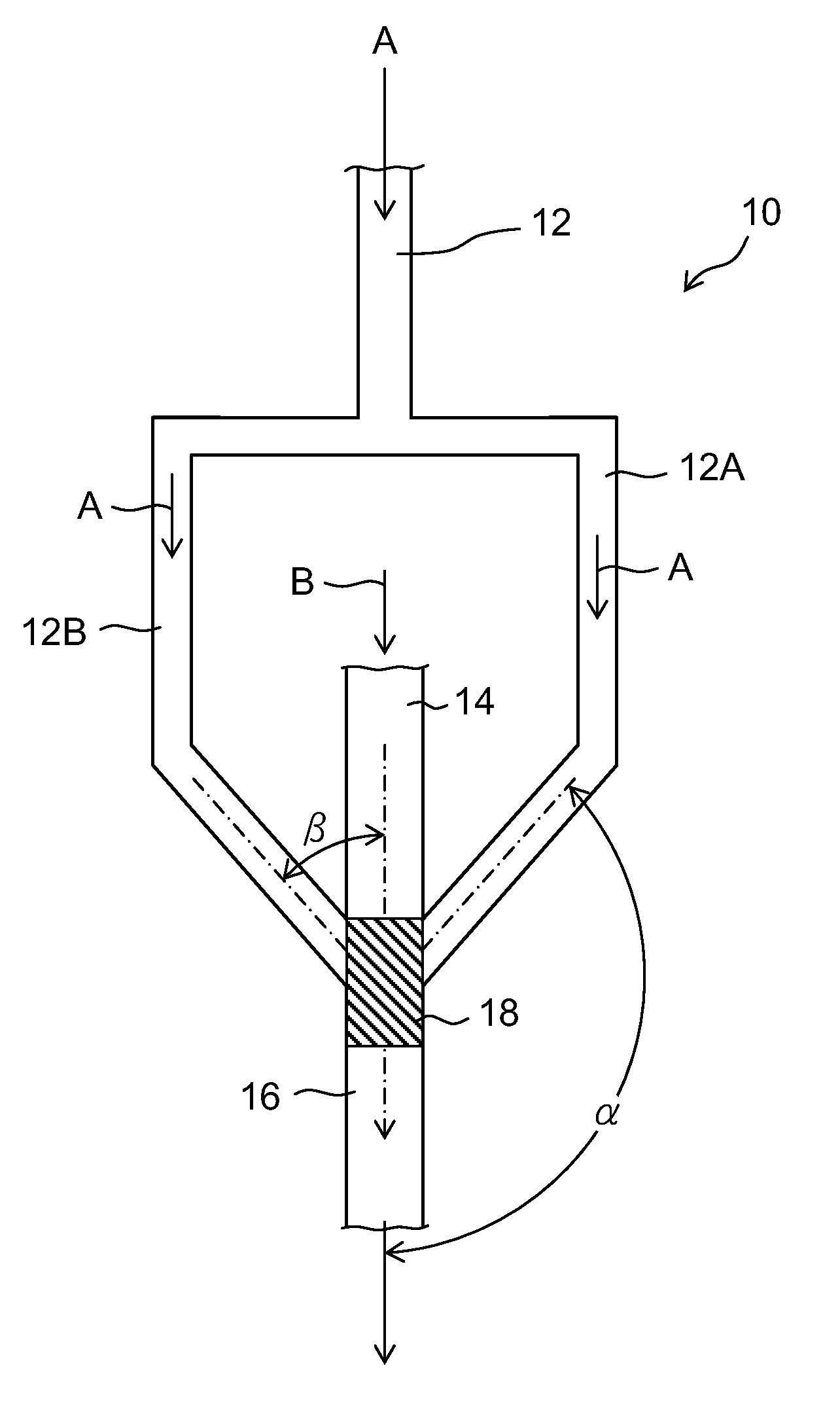
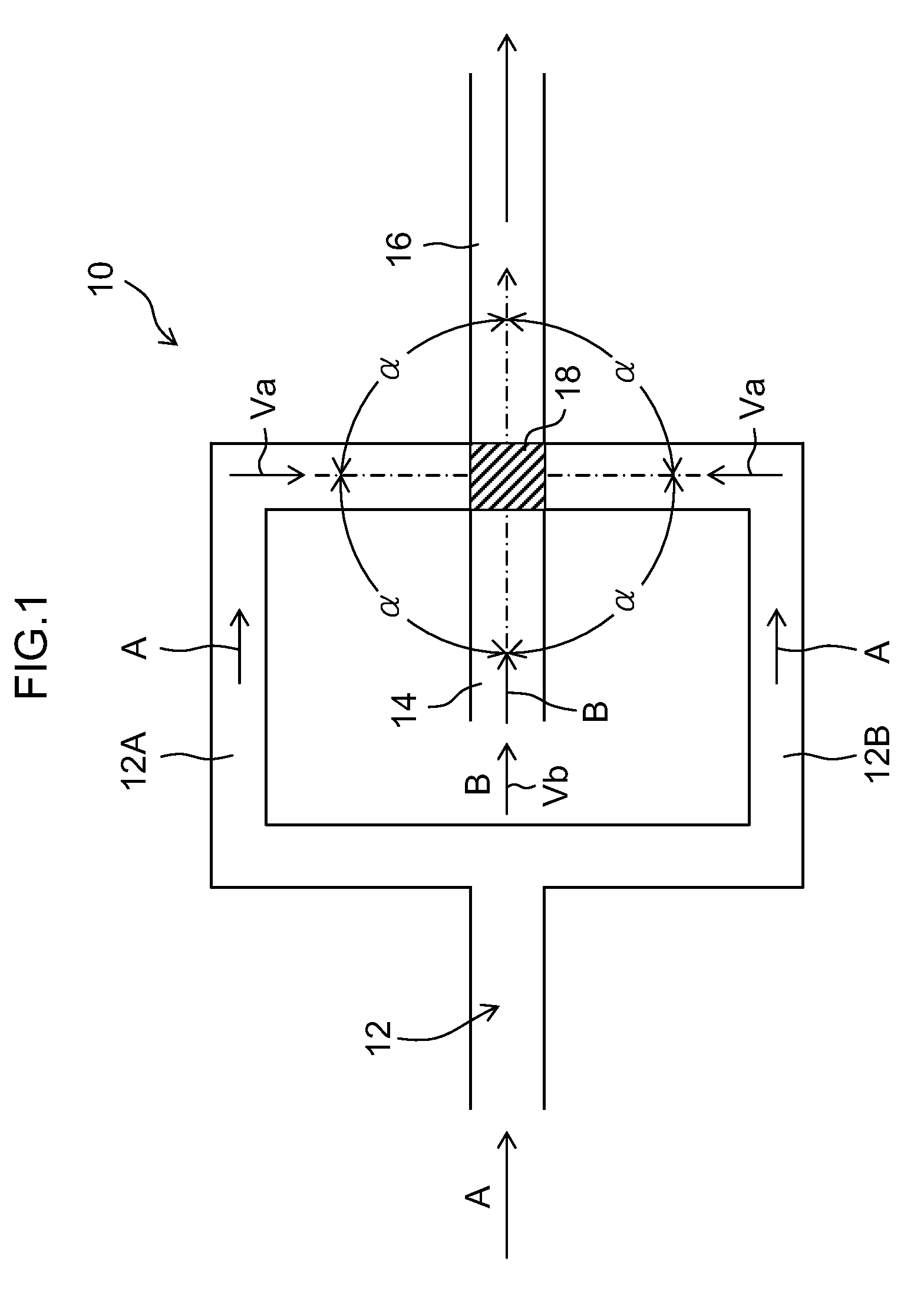
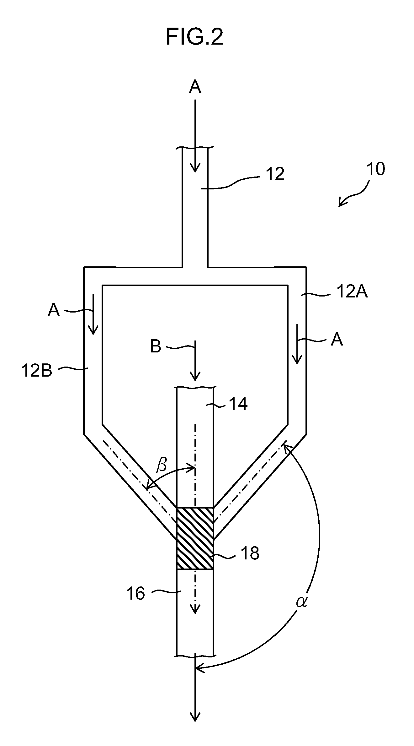
[0125]A first solution and a second solution were sent at a flow rate of 80 ml / min. to 960 ml / min. using the microreactor in which a width of a first passage was 100 μm, a depth thereof was 200 μm, and the number of the passages thereof was five; a width of a second passage was 700 μm, a depth thereof was 200 μm, and the number of the passages thereof was five; a merging section equivalent diameter φ was 1.34 mm and a depth of the merging section was 200 μm; an outlet diameter φ was 0.8 mm; and a mixing zone was 0.28 mm3. As a result, a dynamic pressure reached 199 kPa at 320 ml / min. (the first solution 40 ml / min.:the second solution 280 ml / min.=1:7, the total flow rate per second is 1.9×10⁴ times the volume of the mixing zone), a particle size d50=3.7 nm and distribution Mv / Mn=1.18. At this flow rate or more, the particle size d50 was not more than 5 nm, and the distribution Mv / Mn was not more than 1.3.
example 2
[0126]A first solution and a second solution were sent at a flow rate of 80 ml / min. to 400 ml / min. using the microreactor in which a width of a first passage was 150 μm, a depth thereof was 200 μm, and the number of the passages thereof was three; a width of a second passage was 600 μm, a depth thereof was 200 μm, and the number of the passages thereof was three; a merging section equivalent diameter φ was 0.8 mm and a depth of the merging section was 200 μm; an outlet diameter φ was 0.8 mm; and a mixing zone was 0.10 mm3. As a result, a dynamic pressure reached 124 kPa at 200 ml / min. (the first solution 25 ml / min.:the second solution 175 ml / min.=1:7, the total flow rate per second is 3.3×10⁴ times the volume of the mixing zone), a particle size d50=4.7 nm and distribution Mv / Mn=1.29. At this flow rate or more, the particle size d50 was not more than 5 nm, and the distribution Mv / Mn was not more than 1.3.
example 3
[0127]A first solution and a second solution were sent at a flow rate of 80 ml / min. to 400 ml / min. using the microreactor in which a width of a first passage was 100 μm, a depth thereof was 400 μm, and the number of the passages thereof was three; a width of a second passage was 400μm, a depth thereof was 400 μm, and the number of the passages thereof was three; a merging section equivalent diameter φ was 0.8 mm and a depth of the merging section was 400 μm; an outlet diameter φ was 0.8 mm; and a mixing zone was 0.20 mm3. As a result, a dynamic pressure reached 100 kPa at 240 ml / min. (the first solution 30 ml / min.:the second solution 210 ml / min.=1:7, the total flow rate per second is 2.0×10⁴ times the volume of the mixing zone), a particle size d50=3.1 nm and distribution Mv / Mn=1.23. At this flow rate or more, the particle size d50 was not more than 5 nm, and the distribution Mv / Mn was not more than 1.3.
PUM
| Property | Measurement | Unit |
|---|---|---|
| Pressure | aaaaa | aaaaa |
| Pressure | aaaaa | aaaaa |
| Volume | aaaaa | aaaaa |
Abstract
Description
Claims
Application Information
 - R&D
- Intellectual Property
- Life Sciences
- Materials
- Tech Scout
- Unparalleled Data Quality
- Higher Quality Content
- 60% Fewer Hallucinations
Browse by: Latest US Patents, China's latest patents, Technical Efficacy Thesaurus, Application Domain, Technology Topic, Popular Technical Reports.
© 2025 PatSnap. All rights reserved.Legal|Privacy policy|Modern Slavery Act Transparency Statement|Sitemap|About US| Contact US: help@patsnap.com


