Piezoelectric, micro-exercise apparatus and method

a micro-exercise and piezoelectric technology, applied in the field of bone mass reduction, can solve the problem that bone mass may be lost at a greater rate in absence, and achieve the effect of being easily worn

Active Publication Date: 2011-01-20
PULSE LLC
View PDF58 Cites 41 Cited by
  • Summary
  • Abstract
  • Description
  • Claims
  • Application Information

AI Technical Summary

Benefits of technology

e use of periodic x-rays in assessing the bone density of an immobilized limb may be used to alter the regimen prescribed, and may be used to complete the regimen in body one location, while continuing it in another in order to provide a uniform development of bone mass.[0030]In certain embodiments, an integrated dressing may be used having electromagnetic coils operated by the system in accordance with the invention. Thus, a dressing, a frame, a covering or wrap for the member may each be used individually, or any combination thereof may be used in order to provide electromagnetic flux densities required and the dynamic rising and falling thereof in order to pr
vide the bone density management or intervention required.[0031]In certain embodiments of an apparatus in accordance with the invention, a wear layer or witness layer may be provided on the foot bed or sole of a boot cast. For example, removable boot casts provide a foot bed similar to a shoe. A wear layer may be provided such as a two-layer lamination having a comparatively easily worn off top layer of one color with a more robust substrate therebelow. Thus, if an individual walks prematurely on the boot cast, then the witness layer may show the contrasting color of the substrate through a ruptured or worn off outer portion, thus providing an absolute verification that the foot has been pressuring, wearing, or otherwise active on the foot bed.[0032]In certain embodimen

Problems solved by technology

Moreover, bone mass may be lost at a greater rate in the absence of exercise then it can typically be regained upon resumption of exercise.

Method used


Image

  • Piezoelectric, micro-exercise apparatus and method
  • Piezoelectric, micro-exercise apparatus and method
  • Piezoelectric, micro-exercise apparatus and method

Examples


Embodiment Construction

[0097]It will be readily understood that the components of the present invention, as generally described and illustrated in the drawings herein, could be arranged and designed in a wide variety of different configurations. Thus, the following more detailed description of the embodiments of the system and method of the present invention, as represented in the drawings, is not intended to limit the scope of the invention, as claimed, but is merely representative of various embodiments of the invention. The illustrated embodiments of the invention will be best understood by reference to the drawings, wherein like parts are designated by like numerals throughout.

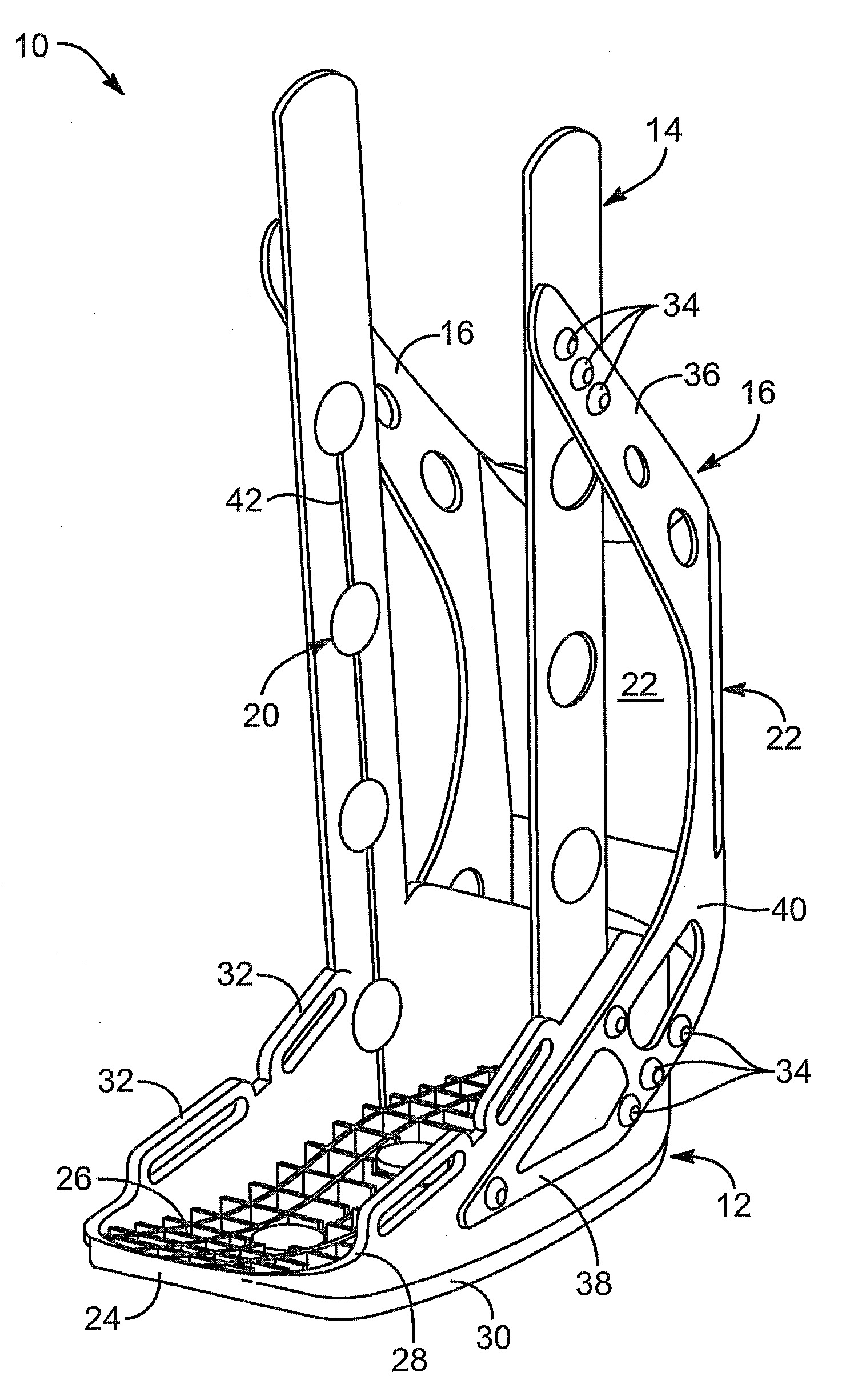
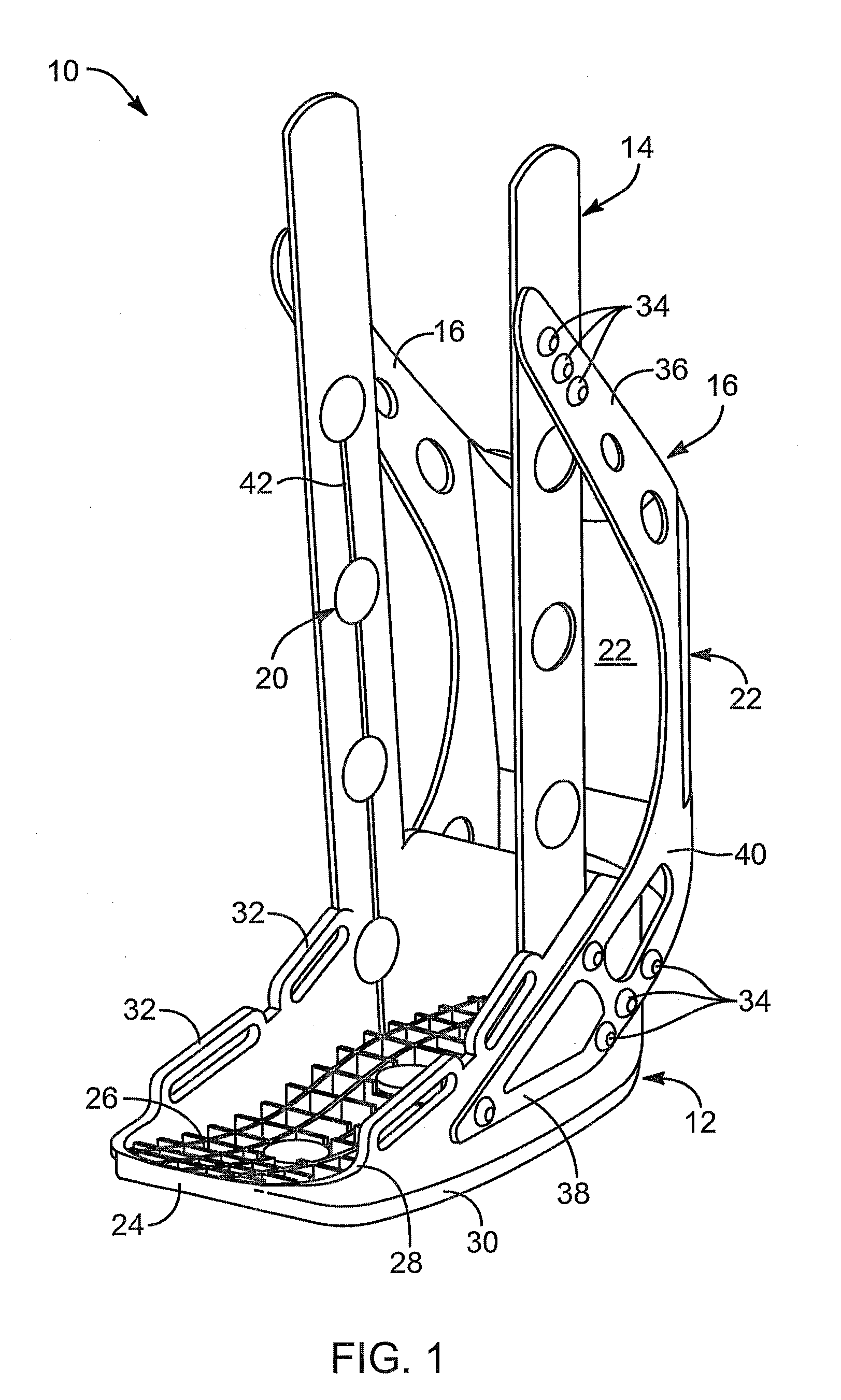
[0098]Referring to FIG. 1, an apparatus 10, such as a boot cast or the frame of a boot cast, may include a base 12. In certain embodiments, the base 12 may be made of plastic or another suitable polymer or reinforced polymer. For example, when the apparatus 10 is a boot cast, the base 12 or portion thereof may serve as the foot ...


PUM


Abstract

An apparatus and method for micro-exercise apply piezoelectric stress to cells of a bone mass by inducing voltages in the bone mass. Application of dynamic, electromagnetic fields passing through the conductive bone mass induce currents and voltages locally in and around cells or groups of cells. The cells respond to the combination of mechanical stress and strain by building themselves up as they would if they had been subjected to the stress and strain of conventional exercise. Thus, micro-exercise at a cellular level of the bone mass can be stimulated as if the stress and strain had been applied to the entire bone structure of which the smaller cellular portions are constituent parts. In combination with casts or splints, the sources of electromagnetic flux may be embedded in the frame or solid structure, the protective padding added for comfort, or both.

Description

BACKGROUND[0001]1. The Field of the Invention[0002]This invention relates generally to reduction in bone mass associated with inactivity, such as occurs whenever a limb is immobilized by a cast for an extended period of time, and more particularly to apparatus and methods to promote exercise on a cellular level when actual exercise motion by the limb is not available.[0003]2. The Background Art[0004]Bones represent a curious structure, often referred to in the prior art as “not well understood.” In space, such as during missions to the moon, extended orbits, work within the space station, during healing of a broken bone immobilized in a cast for typically six weeks or more, and the like, science has studied the loss of bone mass. The lack of exercise appears to relate to the loss of bone mass.[0005]Moreover, bone mass may be lost at a greater rate in the absence of exercise then it can typically be regained upon resumption of exercise. Thus, what is needed is an apparatus and method...

Claims


Application Information

Patent Timeline
Patent Type & Authority Applications(United States)
IPC IPC(8): A61N2/04A61F5/00
CPCA61F5/0111A61F5/0585A61N2/02A61N2/002
Inventor ANDERSON, GREGORY S.HUNTSMAN, KADE E.GLEDHILL, DALE C.BURRELL, DOUGLAS R.XIAO, DAVID
Owner PULSE LLC
Why Eureka
Try Eureka