Shock absorber with dual piston

a dual-piston, shock-absorbing technology, applied in the direction of springs, vibration dampers, springs/dampers, etc., can solve the problems of unpredictability, deformation, unexpected vibrations and noises, etc., to reduce vibration and noise, good centering, and fast opening function

Active Publication Date: 2011-01-27
OHLINS
View PDF10 Cites 28 Cited by
  • Summary
  • Abstract
  • Description
  • Claims
  • Application Information

AI Technical Summary

Benefits of technology

[0020]By configuring the sealing washer with lugs extending radially inward toward the center, a good centering is obtained between the sealing washer and its seat. Moreover, only slight overlap is created between the sealing washer and the seat of the main piston, thereby giving a fast opening function.
[0021]The above-described lugs also mean that a maintained restriction and centering is possible, but with a reduced inner restriction of the flow between the inner edge of the flow limiter and the spacer sleeve around which the flow limiter is centered. The narrow gap which is formed between the inner edge of the flow limiter and the spacer sleeve is in this case significantly shorter in it...

Problems solved by technology

Problems have then arisen, since very soft washers easily become unstable and start to deform unpredictably with the flow.
The whole of the dynamics of the absorber are in this case impaired and unexpected vibrations and noise can arise.
A further problem with shock absorbers produced according to the p...

Method used


Image

  • Shock absorber with dual piston
  • Shock absorber with dual piston
  • Shock absorber with dual piston

Examples


Embodiment Construction

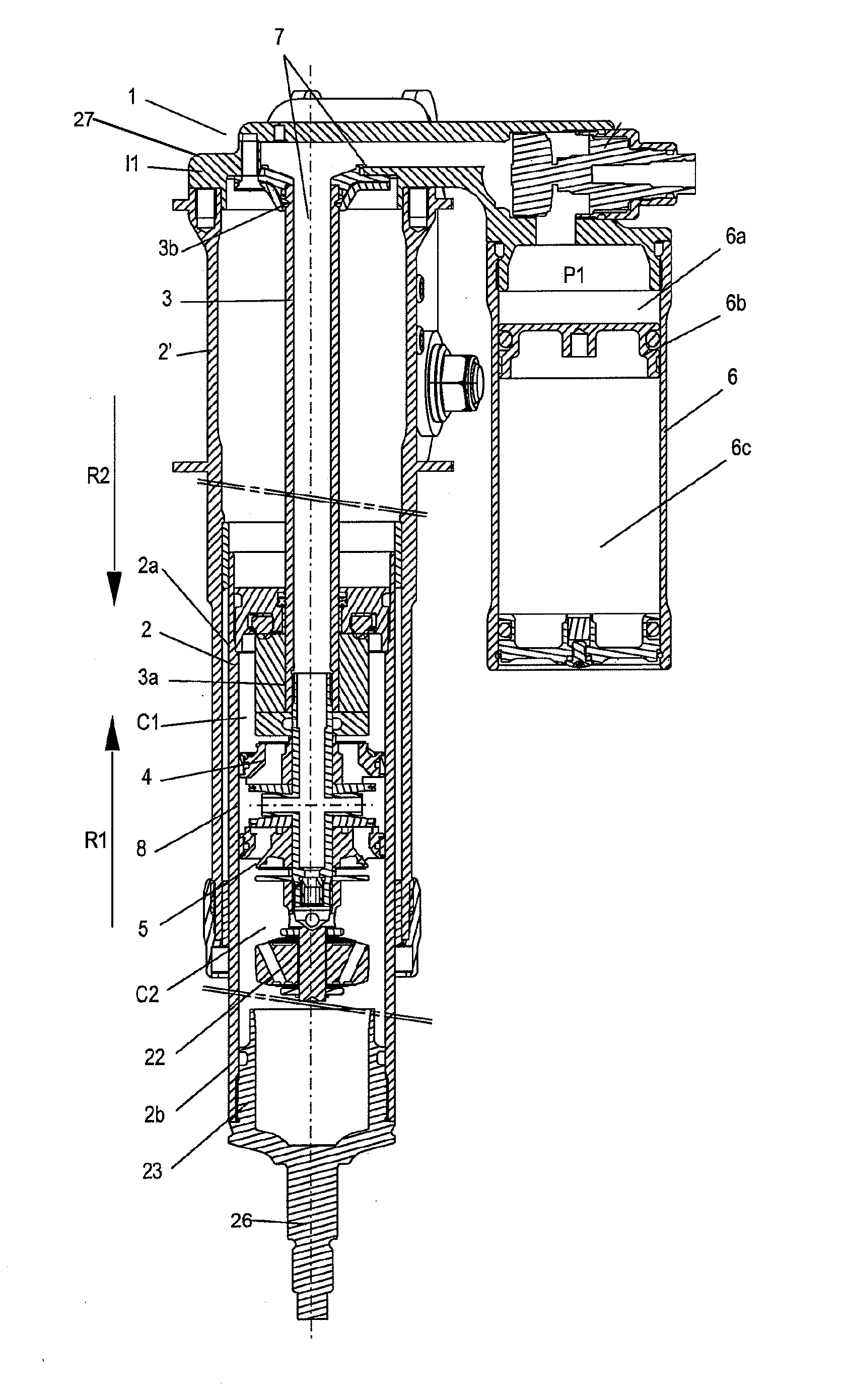
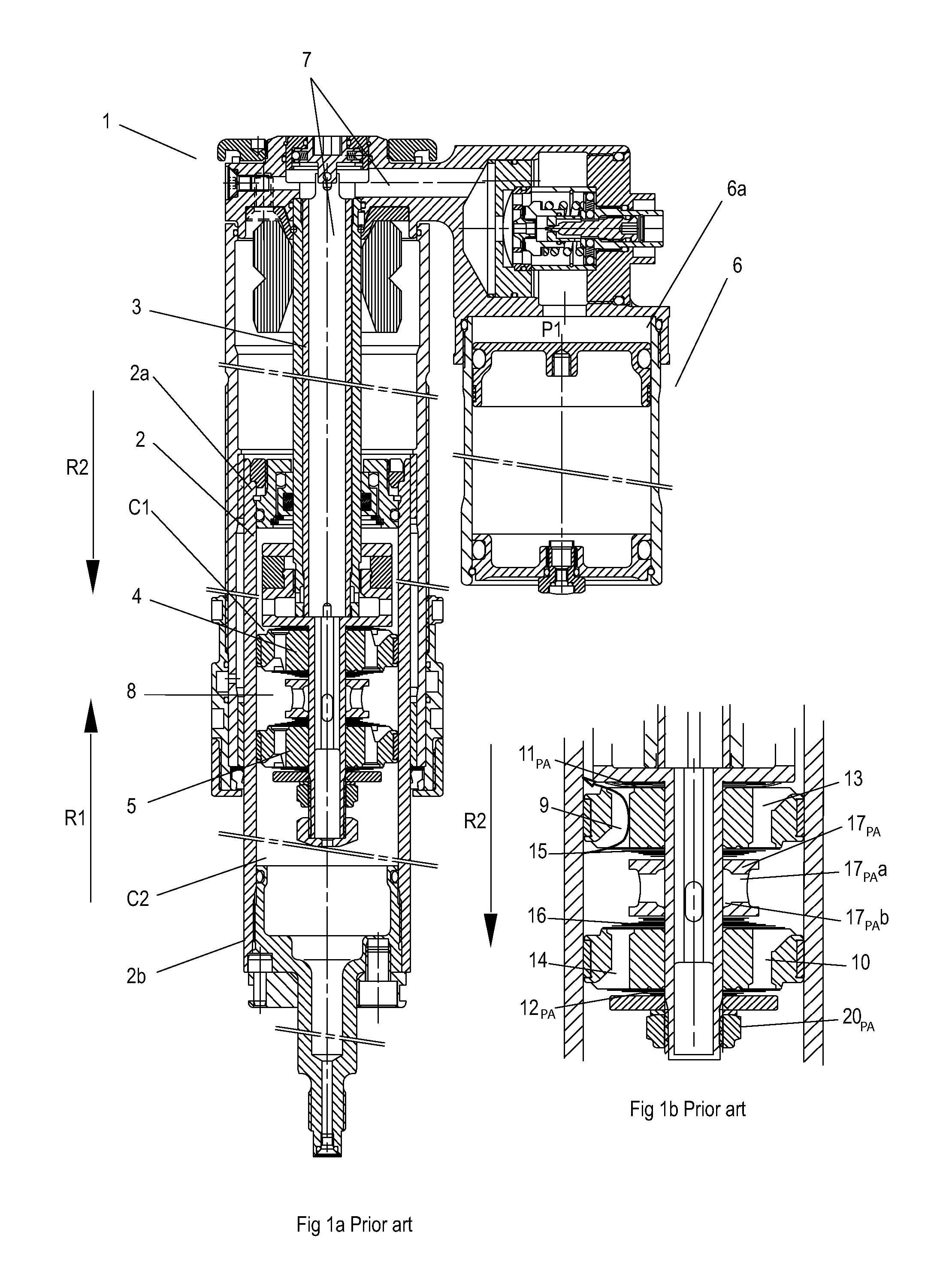
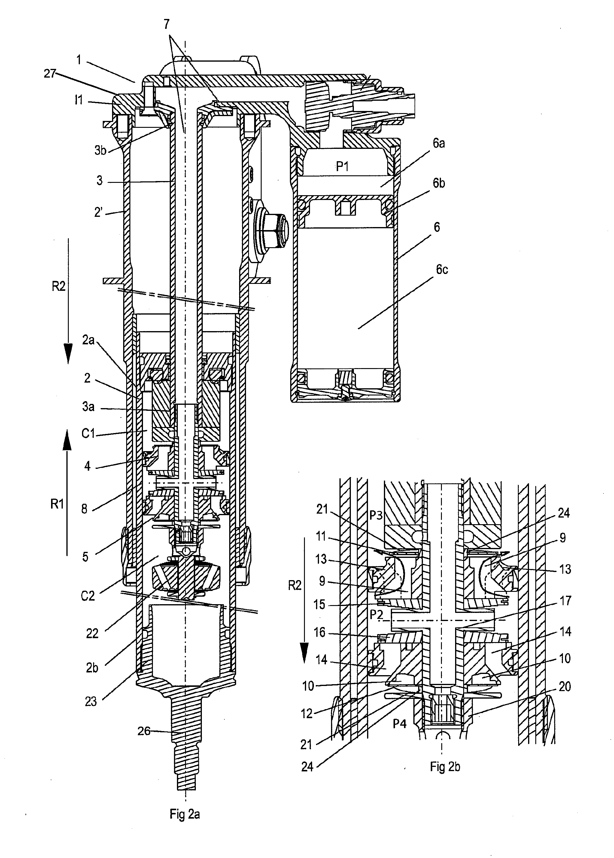
[0037]A shock absorber 1, which is arranged and configured in accordance with certain features, aspects and advantages of the invention, see FIGS. 2a and 2b, as a basic construction corresponding to the prior art shown in FIG. 1. The shock absorber thus comprises a damping-medium-filled damping cylinder body 2, which is delimited at the ends 2a, 2b and is divided into a first damping chamber C1 and a second damping chamber C2 by a main piston device made up of two main pistons 4, 5. The damping medium is preferably hydraulic oil, which can contain associated additives in a manner that is known per se. Alternatively, glycol and / or water can be used as the fluid. The damping cylinder body 2 is preferably also telescopically disposed in a second cylinder 2′.

[0038]The main pistons 4, 5 are mounted on a first end 3a of a hollow piston rod 3, which extends through one of the ends 2a of the cylinder body and which moves with the second cylinder 2′. Through the piston rod 3, damping medium ...


PUM


Abstract

A shock absorber comprising a damping cylinder is divided into a first damping chamber and a second damping chamber by a main piston device. The main piston device comprises a first main piston and a second main piston. The main pistons comprise continuous ducts that are delimited in a direction of flow by first and second flow limiters. The main pistons are mounted on a piston rod. The piston rod has an axially extending and continuous cavity through which damping medium can flow between a pressurized chamber and a respective damping chamber. The damping medium flows via an interspace delimited by the first main piston and the second main piston out into the damping chambers via pressurization ducts delimited by the first flow limiters. The first flow limiters lift axially from the main piston with substantially maintained external form in the opening process so that a flow path is created both between the main piston and the whole or parts of the inner periphery of the first flow limiter as well as between the main piston and the outer periphery of the first flow limiter.

Description

CROSS-REFERENCE TO RELATED APPLICATIONS[0001]This application is a U.S. National Phase of International Application No. PCT / SE2008 / 051484, filed Dec. 17, 2008, which claims priority to Swedish Patent Application No. 0702838-4, which was filed on Dec. 19, 2007.BACKGROUND OF THE INVENTION[0002]1. Field of the Invention[0003]The invention relates to a shock absorber, in which compression and return damping is realized with double pistons and in which pressurization of the absorber is realized between the pistons.[0004]2. Description of the Related Art[0005]The Applicant produces a shock absorber 1, see FIGS. 1 and 1a, comprising a damping-medium-filled cylinder body 2, which is delimited at the ends and is divided into a first damping chamber C1 and a second damping chamber C2 by a main piston device that is made up of two main pistons 4, 5.[0006]The main pistons 4, 5 are mounted on a hollow piston rod 3, which extends through one of the ends 2a of the cylinder body. Through the piston...

Claims


Application Information

Patent Timeline
IPC IPC(8): F16F9/516F16F9/18F16F9/348
CPCF16F9/063F16F9/516F16F9/3405F16F9/3484F16F9/3487F16F9/49F16F9/182F16F9/48
Inventor NYGREN, NILS GORANJARL, JOHAN
Owner OHLINS
Why Eureka
Try Eureka