Pressure reservoir for shock absorber

a technology of pressure reservoir and shock absorber, which is applied in the direction of vibration dampers, resilient suspensions, vehicle springs, etc., can solve the problems of increased pressure in the damping body and the external reservoir, and affecting the working of the shock absorber. , to achieve the effect of faster fall in temperature of the damping medium and the gas, and better and smoother working of the shock absorber

Inactive Publication Date: 2011-01-27
OHLINS
View PDF6 Cites 25 Cited by
  • Summary
  • Abstract
  • Description
  • Claims
  • Application Information

AI Technical Summary

Benefits of technology

[0012]The invention further aims to gives a better and smoother working of the shock absorber by allowing a faster fall in temperature of the damping medium and the gas.

Problems solved by technology

It has therefore proved to be a problem to accommodate a vehicle shock absorber with an external reservoir in the diminishing space between the chassis / body and the ground.
The length of the hoses means, however, that there are delays in the system and cavitation can occur more easily.
It can also be a problem to cool both the damping medium and the gas volume when the pressure reservoir has a circular cross section and thus a relatively small area that contacts the cooling external air.
When the shock absorber is subjected to strong forces or high speeds for a lengthy period, the temperature of both the damping medium and the gas increases, which leads to an increase in pressure in the damping body and in the external reservoir.
But because the volume of the gas also changes with a change in temperature, the total pressure in the shock absorber increases and an increased pressure can result in a change to the damping characteristics of the shock absorber.
The result, however, is that the gas volume becomes too small when the temperature of the gas falls.
It has been shown, however, that the fact that the cooling area has a circular profile is not sufficient to optimally cool the damping medium and the gas.

Method used


Image

  • Pressure reservoir for shock absorber
  • Pressure reservoir for shock absorber
  • Pressure reservoir for shock absorber

Examples


first embodiment

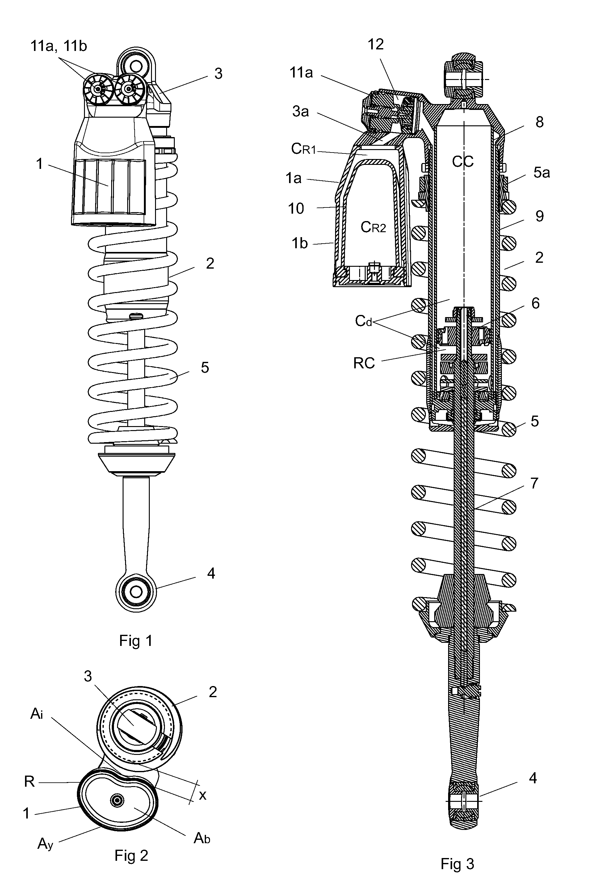
[0032]The inner surface Ai substantially follows the cylindrical shape of the damping body 2 at a radial distance x from the outer diameter of the damping body and this distance is substantially constant over the whole of the inner surface Ai. The distance can vary, but in the invention it must be of such a size that a helical spring 5 can be introduced between the damping body 2 and the reservoir 1. The helical spring 5 must also be able to be compressed without risk of becoming jammed between the parts. Preferably, the distance x is between 10 mm and 20 mm. The distance is adapted to the spring dimensions by variation of the construction of the upper fastening device 3.

[0033]FIG. 3 shows the hydraulic shock absorber having the external reservoir 1 in cross section. The shock absorber is made up of the cylindrical shock absorber body 2 comprising a damping cylinder 8 which delimits an inner damping-medium-filled damping chamber Cd and comprises a main piston 6 fixed to a piston rod...

second embodiment

[0043]In the reservoir 1 according to the invention, which is shown in FIG. 6, the reservoir 1 is extruded from a material so that the reservoir has mutually parallel sides. The upper reservoir part 1a has the form of a separate cap 23, which is sealed against and fastened to the lower reservoir part 1b either with press-fitting or with a threaded or bolted joint. Extending through this cap 23 is the hole connecting the reservoir and the respective damping chamber. The lower reservoir part 1a can also be fixed directly in the cylinder head 3, without the intermediate cap, through mutual matching of the bearing surfaces of the parts.


PUM


Abstract

A reservoir comprises an upper reservoir part and a lower reservoir part divided by a member into a first reservoir chamber and second reservoir chamber. The reservoir mounts to a shock absorber having a generally cylindrical body. At least the lower reservoir part is delimited by two parallel-displaced flat base surfaces and has a reservoir wall as a contacting surface between these base surfaces. The reservoir has a vertical extent that is substantially parallel with the shock absorber body. One of or both of the base surfaces of the lower reservoir part are kidney-shaped and are connected by the reservoir wall so that the lower pat of the reservoir has a vertical extent that partially follows the cylindrical shape of the shock absorber body

Description

CROSS-REFERENCE TO RELATED APPLICATIONS[0001]This application is a U.S. National Phase of International Application No. PCT / SE2008 / 050565, filed May 14, 2008, which claims priority to Swedish Patent Application No. 0701175-2, which was filed on May 16, 2007.BACKGROUND OF THE INVENTION[0002]1. Field of the Invention[0003]The invention relates to a vessel or reservoir that is intended to pressurize a hydraulic shock absorber or a front fork on a two-wheeled or four-wheeled vehicle.[0004]2. Description of the Related Art[0005]Hydraulic shock absorbers having an external reservoir secured to a cylinder head that is connected to the shock absorber body, a so-called “piggyback solution,” have long been known. The external reservoir is intended to pressurize the damping medium in the shock absorber so that a certain excess pressure prevails and cavitation can be avoided. In addition, the pressurizing reservoir can absorb the piston rod displacement of damping medium or the damping medium i...

Claims


Application Information

Patent Timeline
Patent Type & Authority Applications(United States)
IPC IPC(8): F16F9/096F16F9/06B60G17/04
CPCB60G13/08B60G15/062F16F9/096B60G2202/312B60G2202/24
Inventor SINTORN, TORKEL
Owner OHLINS
Why Eureka
Try Eureka