Rectangular sedimentation system having self-aggregation facility

Inactive Publication Date: 2011-01-27
ECODIGM +1
View PDF10 Cites 6 Cited by
  • Summary
  • Abstract
  • Description
  • Claims
  • Application Information

AI Technical Summary

Benefits of technology

[0013]The present invention provides a rectangular sedimentation tank with improved sedimentation efficiency and/or reduced m

Problems solved by technology

The conventional rectangular sedimentation tank, however, has problems.
For example, it requires long sedimentation retention time to treat water with high SS density.
As a cons

Method used


Image

  • Rectangular sedimentation system having self-aggregation facility
  • Rectangular sedimentation system having self-aggregation facility
  • Rectangular sedimentation system having self-aggregation facility

Examples


examples

[0058]The present invention will now be in more detail described in the numerical analysis example below.

[0059]A computing turbulence analysis was carried out to understand variations of a turbulent flow in the sedimentation tank according to the present embodiment.

[0060]The specification and the operating condition used for the analysis is listed in Table 1.

TABLE 1ItemConditionRemarkFlux300,000 ton / dayAnalysisSize of7.4 mW × 60 mL ×program,:sedimentation2.6 mH × 16 basinFluent 6.2basinFlux of one 18.750 ton / daybasin

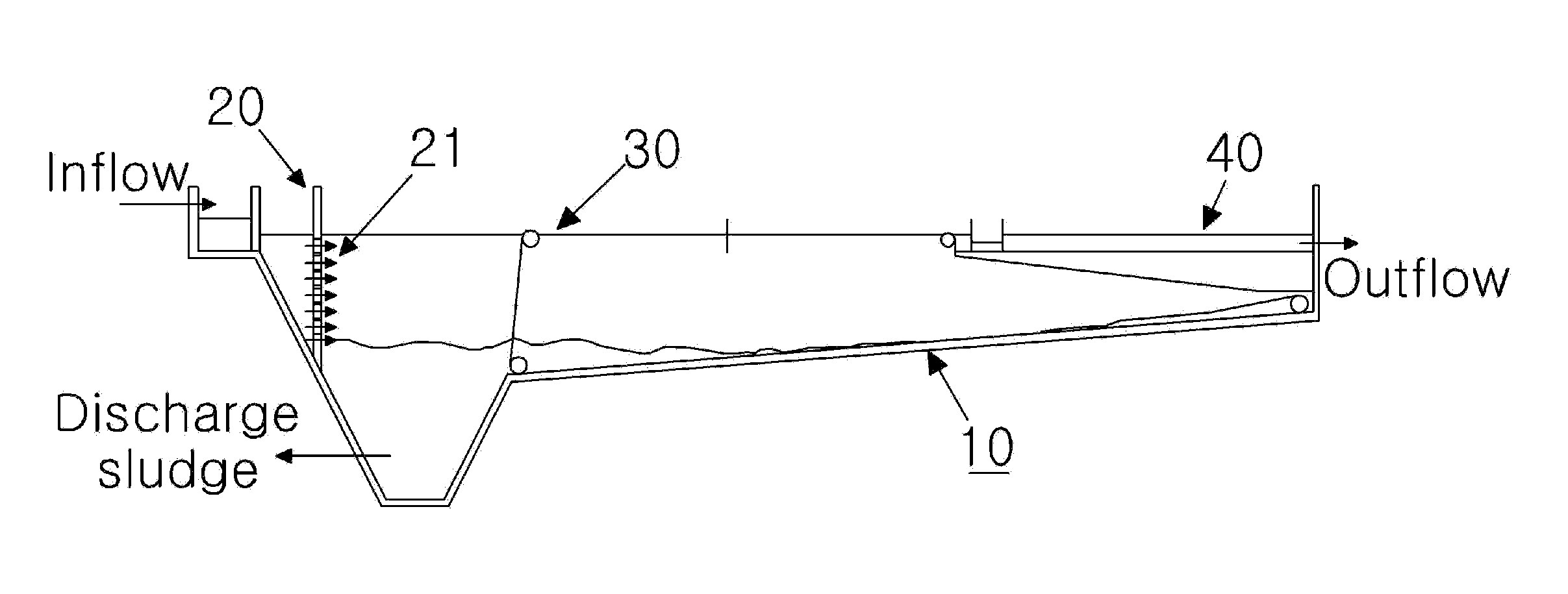
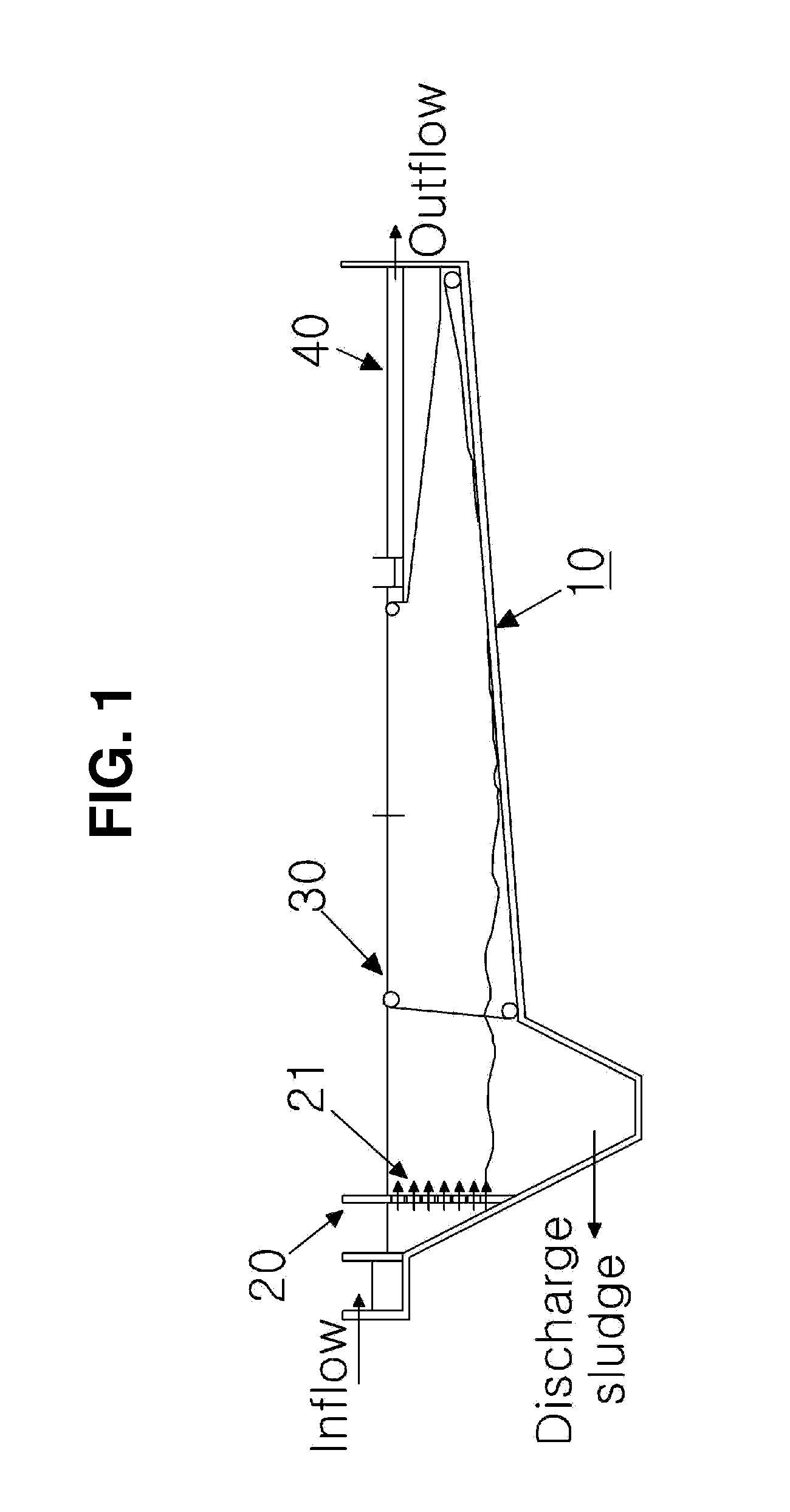
[0061]FIG. 6 shows a computing simulation of sludge movement (i.e., density of sludge according to position) in a conventional rectangular sedimentation tank. FIG. 7 shows a computing simulation of sludge movement in a rectangular sedimentation tanks according to an embodiment of the present invention, in which a sludge movement prevention baffle is not included. FIG. 8 shows a computing simulation of sludge movement in a rectangular sedimentation tank according to an em...


PUM

PropertyMeasurementUnit
Fractionaaaaaaaaaa
Fractionaaaaaaaaaa
Angleaaaaaaaaaa

Abstract

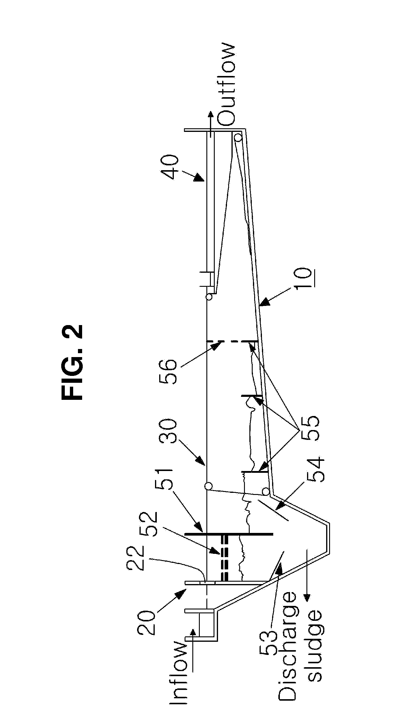
A rectangular sedimentation tank includes a hopper portion in an upstream side and a floor inclination portion in a downstream side. The tank comprises: a vertical baffle formed at a side portion of the hopper portion; a vertical screening plate provided in a position corresponding to about 30 to 100% of a horizontally cross-sectional area of top of the hopper portion; and a horizontal baffle provided between the vertical baffle and the vertical screening plate. With the tank, contaminated water can be treated cost-effectively and efficiently.

Description

CROSS-REFERENCE TO RELATED APPLICATION[0001]This is a continuation of International Application No. PCT / KR2009 / 001506, with an international filing date of Mar. 25, 2009, which claims the benefit of Korean Application No. 10-2008-0027179 filed Mar. 25, 2008, the entire contents of which are incorporated herein by reference.TECHNICAL FIELD[0002]The present invention relates to a structure of a sedimentation tank for use in treating contaminated water (waste water). More particularly, it relates to a rectangular sedimentation system having a self-aggregation facility that can induce suspended solids (SS) contained in contaminated water to be self-aggregated, thereby increasing sedimentation efficiency and overall treatment efficiency.BACKGROUND ART[0003]A typical apparatus for treating foul water and / or waste water includes a storage tank in which contaminated water to be treated is filled, a processing tank for purifying by using a biological method and / or a chemical method the conta...

Claims


Application Information

Patent Timeline
IPC IPC(8): B01D21/02C02F1/00
CPCB01D21/0042B01D21/2422B01D21/04B01D21/02
Inventor KWON, JUNG CHUN
Owner ECODIGM
Why Eureka
Try Eureka