Heating element and manufacturing method thereof

a technology of heating element and manufacturing method, which is applied in the direction of vehicle maintenance, vehicle cleaning, transportation and packaging, etc., can solve the problems of difficult to drive it at a low voltage of 40 v or less, and achieve excellent heating performance, low voltage, and minimal side effects.

Active Publication Date: 2011-01-27
LG CHEM LTD
View PDF29 Cites 29 Cited by
  • Summary
  • Abstract
  • Description
  • Claims
  • Application Information

AI Technical Summary

Benefits of technology

[0006]According to the exemplary embodiments of the present invention, the heating element can minimize side effects by diffraction and interference of single light source after sunset, has excellent heating performance at a low voltage and is not well visible. In addition, according to the exemplary embodiments of the pr

Problems solved by technology

However, the heating glass according to the above method has a problem in that it is di

Method used


Image

  • Heating element and manufacturing method thereof
  • Heating element and manufacturing method thereof
  • Heating element and manufacturing method thereof

Examples


example 1

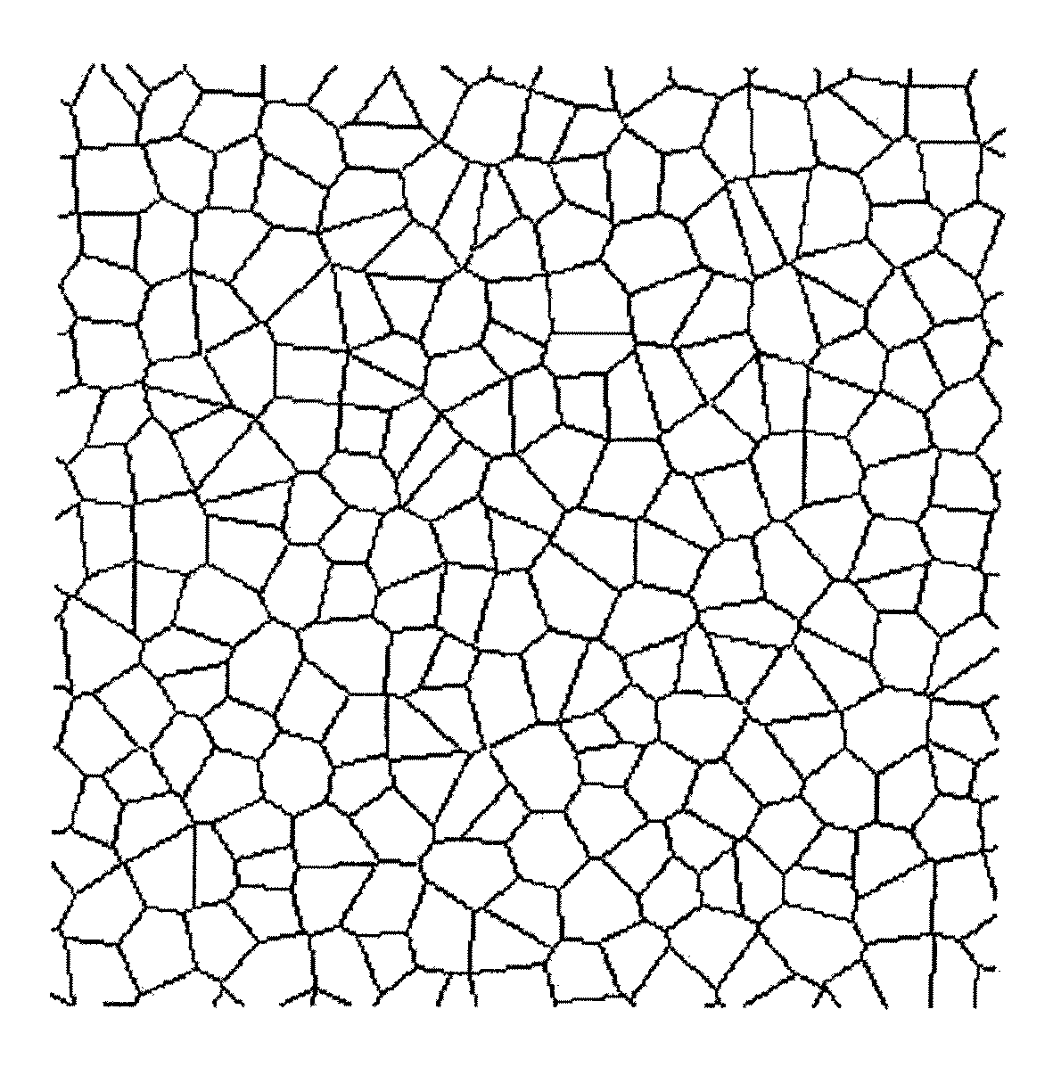
[0084]The silver paste was manufactured by dissolving 80 wt % of silver particles that had the particle diameter of 2 micrometers, 5 wt % of polyester resin, 5 wt % of grass frit in 10 wt % of RCA (butyl carbitol acetate) solvent. As the intaglio, the glass that had the width of 20 micrometers, the depth of 7.5 micrometers and the Voronoi pattern was used. The Voronoi pattern that was the same as that of FIG. 1 was manufactured by setting the square of 0.09 mm2 as the basic unit and providing irregularity to the distribution of dots in the basic unit. The ratio of the area distribution of the closed figure of the pattern was 23%.

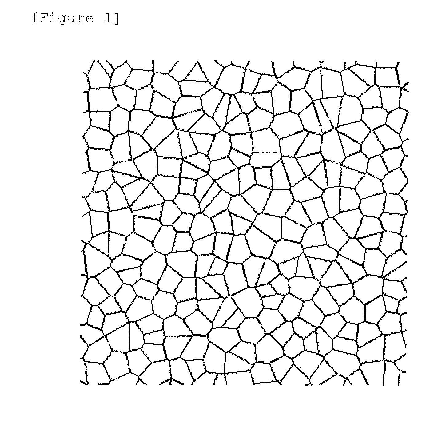
[0085]After the silver pattern was formed on the glass substrate (100 mm×100 mm) by using the method that was shown in FIG. 2 and the offset printer, it was sintered at 600° C. for about 3 min to form the pattern shown in FIG. 1. The surface resistance of the glass substrate was 0.6 ohm / square, and the bus bar was formed by contacting the copper strip on the...

example 2

[0087]The silver paste was manufactured by dissolving 80 wt % of silver particles that had the particle diameter of 2 micrometers, 5 wt % of polyester resin, 5 wt % of grass frit in 10 wt % of BCA (butyl carbitol acetate) solvent. As the intaglio, the glass that had the width of 20 micrometers, the depth of 10 micrometers and the Delaunay pattern was used. The Delaunay pattern as shown in FIG. 8 was manufactured after being formed by making the distribution of dots in the basic unit 0.09 mm2 irregular. The ratio of the area distribution of the closed figure of the pattern was 20%.

[0088]After the silver pattern was formed on the glass substrate (100 mm×100 mm) by using the method that was shown in FIG. 2 and the offset printer, it was sintered at 600° C. for about 3 min to form the pattern shown in FIG. 8. The surface resistance of the glass substrate was 1.0 ohm / square, and the bus bar was formed by contacting the copper strip on the pattern by the clip in the direction of 100 mm. I...

example 3

[0089]The same method as Example 1 was performed, except that only the basic unit was changed into 0.25 mm2. In this case, the used pattern was the same as FIG. 9. The ratio of the area distribution of the closed figure of the pattern was 20%. In this case, the surface resistance was 1.2 ohm / square, and resistance between both ends of the glass substrate of 100 mm×100 mm was 1.5 ohm. The visible ray permeability of the glass that had the conductive heating line pattern was 83%. In this case, the standard deviation value of the intensity of light for each angle was 1.4. In addition, predetermined patterns by scattering of light were not observed around the light source.


PUM

PropertyMeasurementUnit
Lengthaaaaaaaaaa
Fractionaaaaaaaaaa
Fractionaaaaaaaaaa

Abstract

Provided are a heating element that includes: a transparent substance; a conductive heating line that is provided on at least one side of the transparent substance; bus bars that is electrically connected to the conductive heating line; and a power portion that is connected to the bus bars, wherein 30% or more of the entire area of the transparent substance has a conductive heating line pattern that is formed of closed figures where a distribution is continuous and a ratio (area distribution ratio) of a standard deviation in respects to an average value of areas of the closed figures is 2% or more, and a method for manufacturing the same.

Description

TECHNICAL FIELD [0001]The present invention relates to a heating element and a method for manufacturing the same. More particularly, the present invention relates to a heating element that includes a pattern that is not well visible, has excellent heating performance at a low voltage, and is capable of minimizing diffraction and interference of light, and a method for manufacturing the same.BACKGROUND ART [0002]In winter or rainy day, frost is formed on a glass surface of a vehicle because of a difference between temperatures of the outside and inside of the vehicle. In addition, in the case of an indoor ski resort, a freezing phenomenon occurs because of a difference between temperatures of the inside where there is a slope and the outside of the slope. In order to solve this, a heating glass has been developed. The heating glass uses a concept where after a hot line sheet is attached to the glass surface or a hot line is directly formed on the glass surface, a current is applied t...

Claims


Application Information

Patent Timeline
IPC IPC(8): H05B3/10
CPCC03C17/34H05B2203/017H05B3/84B60S1/02
Inventor CHOI, HYEONKIM, SU-JINHWANG, JI-YOUNGOH, SEUNG-TAEKIM, KI-HWANCHUN, SANG-KIHONG, YOUNG-JUNHWANG, IN-SEOKLEE, DONG-WOOK
Owner LG CHEM LTD
Why Eureka
Try Eureka