Wind turbine

a wind turbine and turbine blade technology, applied in the direction of electric generator control, machines/engines, mechanical equipment, etc., to achieve the effect of reducing cost, improving reliability, and building more economically

Inactive Publication Date: 2011-01-27
ENER2
View PDF54 Cites 55 Cited by
  • Summary
  • Abstract
  • Description
  • Claims
  • Application Information

AI Technical Summary

Benefits of technology

[0014]The embodiments described herein provide a turbine wherein the generator, gearbox and other major components are located at a lower altitude relative to the top of the tower, or even at ground level. As a result of the present invention, the tower is not as top heavy as conventional turbines and can be built more economically. Also, the components can be designed without a need to reduce cost, thereby likely making such components more reliable. And, maintenance of the present invention is much less expensive and less dangerous than with traditional turbines.
[0015]The erection of a turbine and all its associated costs, i.e., the erection of ancillary structures, the use of heavy duty cranes, and the transportation of such equipment to the site, constitute a major cost factor in a turbine project. These cost can be substantially reduced by using the solutions provided in the embodiments described herein.
[0016]Additionally, through the use of the concepts provided for in the embodiments herein, the components located at the bottom of the tower do not need to be optimized for weight and size in their design and manufacture. They can be made sturdy, reliable and inexpensive; no need for special high-strength, low-weight materials and complex low-weight and compact designs. Once weight is removed as a key design criteria, cost can be substantially reduced while simultaneously increasing reliability to levels not possible in prior art designs.
[0017]A further advantage of the embodiments herein is the possibility of eliminating the drive transmission, and directly driving the generator from the bottom drum. Such direct drive generally requires a large diameter generator in order to achieve the relatively high relative speed between the rotor and the stator needed for electricity generation. Such a large diameter is a problem when the generator is located on top of a high tower, because of weight, size and the difficulty of maintaining an accurate constant gap between rotor and stator in a large diameter light-weight generator. However, when the generator is placed at the bottom of the tower according to the present invention, weight and size are not a key issue anymore, and the generator can be designed and built in a sturdy and rigid way with all necessary reinforcements, surrounding structures and provisions to achieve a constant gap and reliable operation.

Problems solved by technology

The erection of a turbine and all its associated costs, i.e., the erection of ancillary structures, the use of heavy duty cranes, and the transportation of such equipment to the site, constitute a major cost factor in a turbine project.

Method used


Image

  • Wind turbine
  • Wind turbine
  • Wind turbine

Examples


Embodiment Construction

[0059]While this invention is susceptible of embodiments in many different forms, there is shown in the drawings and will herein be described in detail preferred embodiments of the invention with the understanding that the present disclosure is to be considered as an exemplification of the principles of the invention and is not intended to limit the broad aspect of the invention to the embodiments illustrated.

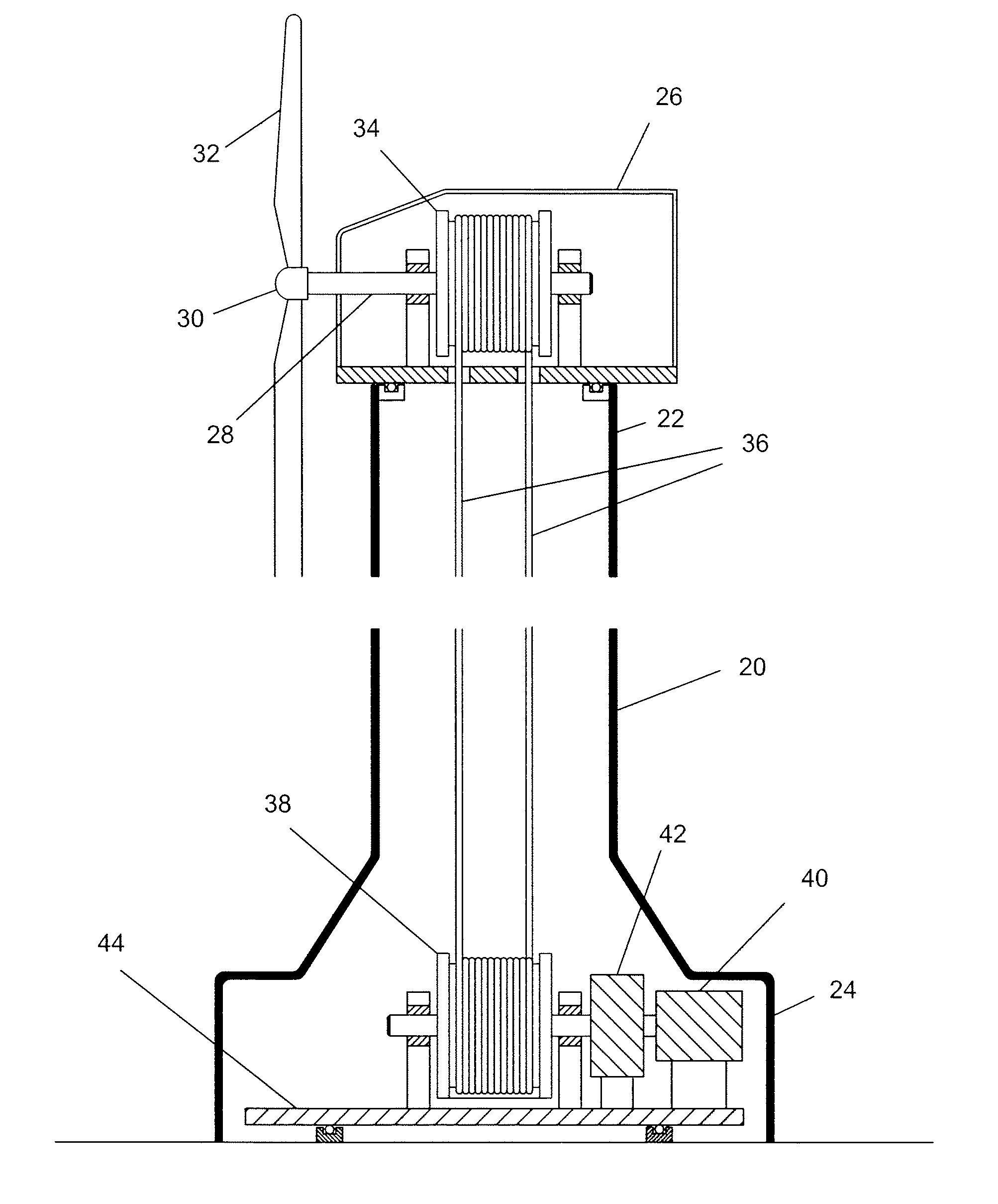
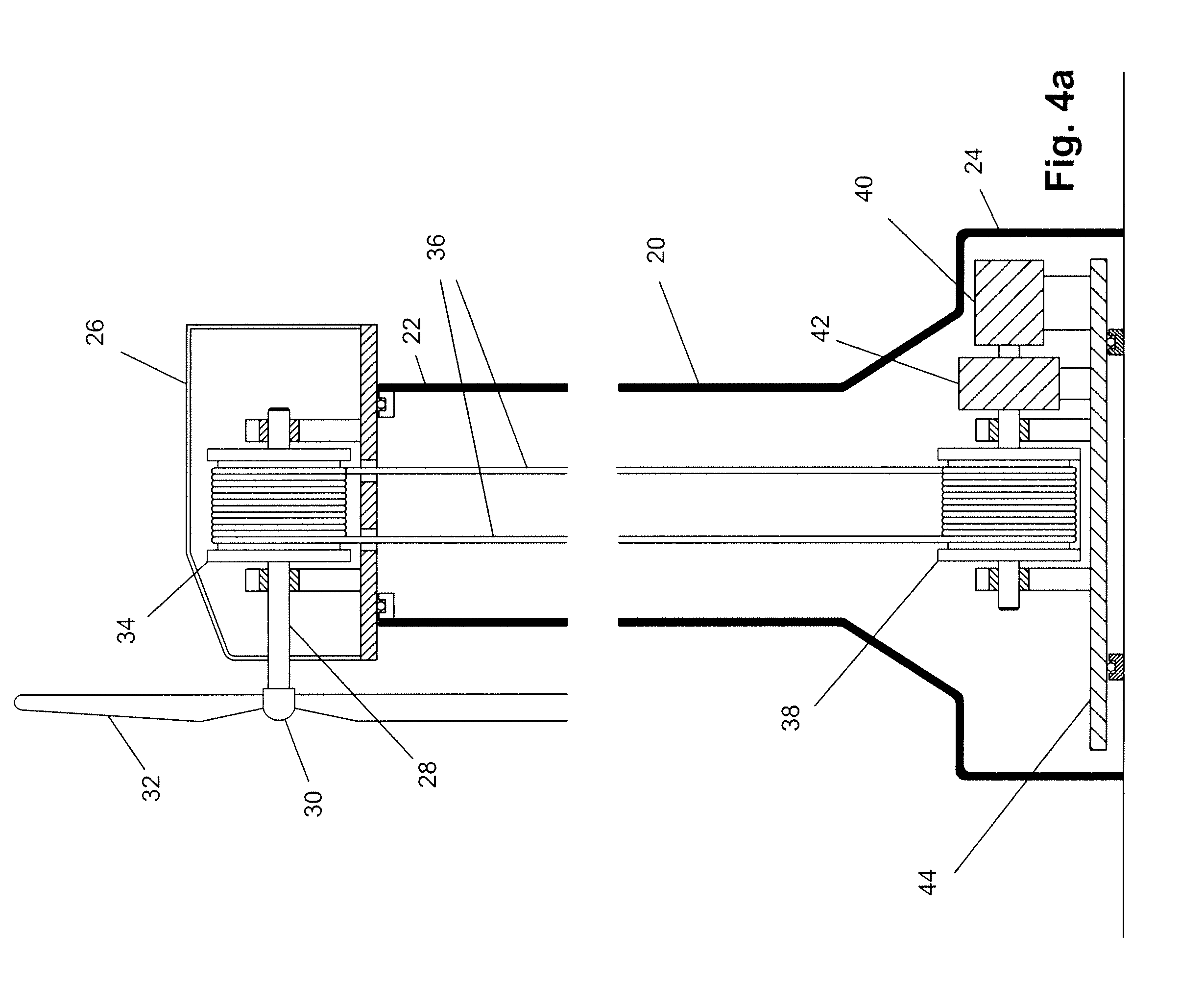
[0060]Referring now to the drawings, and specifically to FIGS. 4a and 4b, there is shown one of the preferred embodiments of the present turbine system to generate electricity from wind energy, which is based on a tower 20 that is fixed in its position with respect to the ground and is therefore non-rotatable. The tower 20 has a top portion 22 and a bottom portion 24. Preferably, the tower has no cables or other supporting structure connecting the tower to the ground other than near its bottom portion 24. Additional supporting structure, such as a lattice or frame, connected to...


PUM


Abstract

A wind turbine system is provided to generate electricity from wind energy. The system locates generator at a bottom portion of the tower. The system rotates either the entire tower, or the nacelle and the generator simultaneously. A flexible power transfer member inside the tower connects a top rotation transfer member and the bottom rotation transfer member to transfer wind energy captured by the turbine rotor from the top rotation transfer member to the bottom rotation transfer member. A pitch mechanism to rotate the rotor blades in a desired angular position about the rotor blades longitudinal axis is also provided.

Description

CROSS-REFERENCE TO RELATED APPLICATIONS[0001]This application claims priority to U.S. Provisional Patent Application No. 61 / 271,406, filed Jul. 21, 2009, which is hereby incorporated by reference and made a part hereof.FEDERALLY SPONSORED RESEARCH OR DEVELOPMENT[0002]Not Applicable.TECHNICAL FIELD[0003]The present invention is related to the industry of alternative energy production and more specifically the industry of turbines for the generation of electricity from the power of the wind.BACKGROUND OF THE INVENTION[0004]Wind turbines are well known mechanical devices that have been used for hundreds of years to perform various types of mechanical work. In modern times the generation of electricity using wind turbines has developed into a large industry.[0005]Referring to FIGS. 1-3, there is shown a traditional prior art turbine 10. Traditional turbines 10 have typically three rotor blades 12 fixedly mounted on a hub 14 rotating about a horizontal axis. The turbine is rotatably atta...

Claims


Application Information

Patent Timeline
Patent Type & Authority Applications(United States)
IPC IPC(8): H02P9/04F03D9/00
CPCF03D7/0204F03D7/0224F03D11/02F03D11/024Y02E10/725F05B2260/403F05B2260/79Y02E10/722Y02E10/723F05B2260/4021F03D9/25F03D15/00F03D15/10Y02E10/72
Inventor MOSER, GEORGELINN, RANDY W.WALWORTH, VANYORK, JEROME B.SHZLOW, LISA
Owner ENER2
Why Eureka
Try Eureka