
Positioning of mobile objects based on mutually transmitted signals

Active Publication Date: 2011-01-27
AIRISTA FLOW INC +1
View PDF5 Cites 67 Cited by
  • Summary
  • Abstract
  • Description
  • Claims
  • Application Information

AI Technical Summary

Benefits of technology

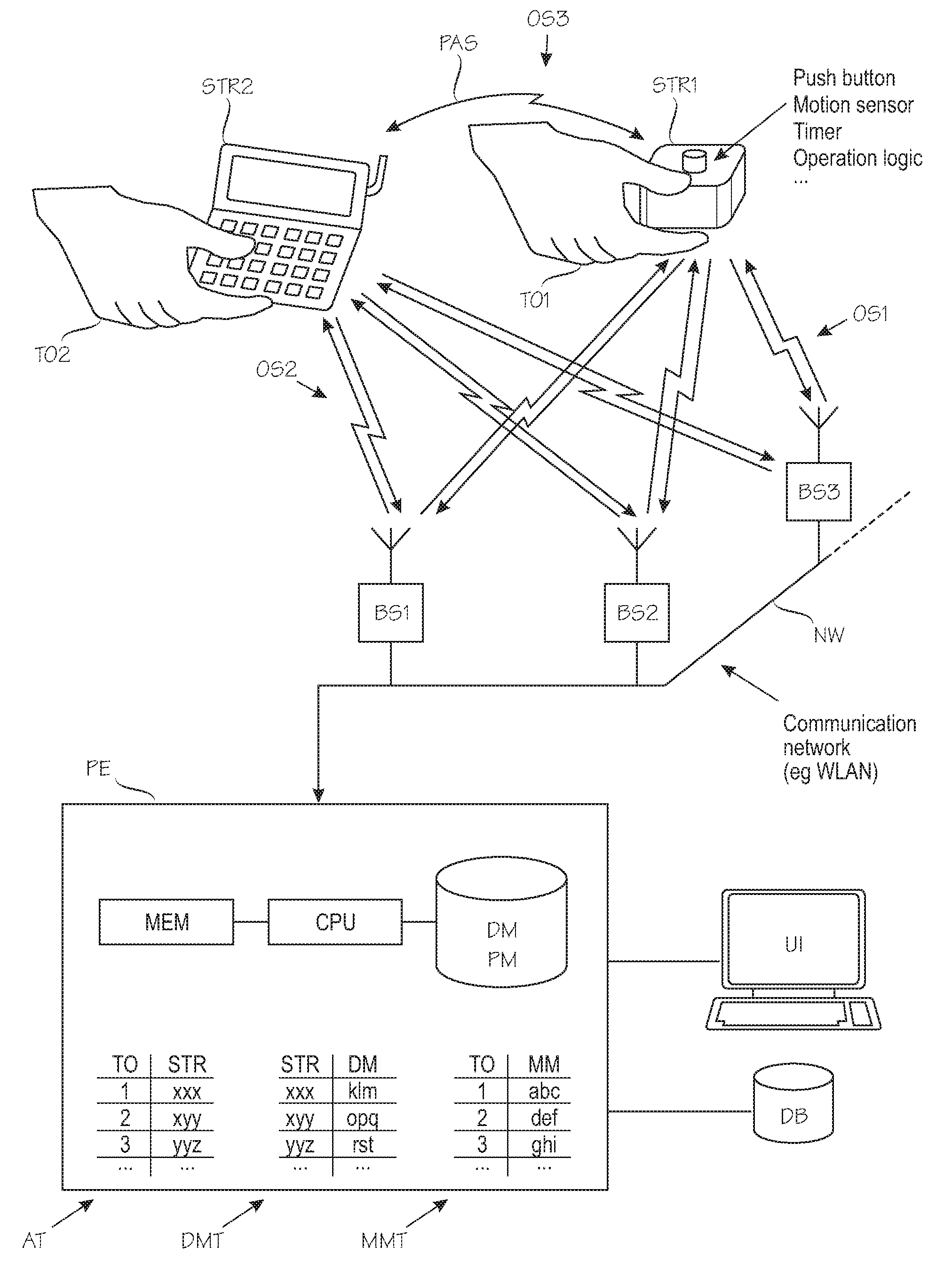
[0036]The invention is partially based on the idea that the requirement for accurate and reliable tag positioning varies over time. In most tag positioning applications, the tag's position is virtually irrelevant when nobody needs to find the tag or the object / person co-located with it. Conversely, the need for the tag's position estimate to be accurate and reliable is highest when there is a need to find or locate the tag. The invention is also based on the idea that determination of the location estimate for the target object can be improved by sending and observing positioning-assisting signals between a first target object and a second target object. In such situations it is possible to improve positioning of a first target object by using observations from another location occupied by a second target object. The mutual positioning-assisting signals sent from one mobile target object and received by another mobile target object provides new type of information which has not been utilized in prior art positioning systems.
[0042]A definite advantage can be achieved by implementing the controller and the operation logic in the tag, preferably in its firmware, so that the tag's scheduled wake-up time is adjusted according to the operation logic. Once the tag is activated, the controller sends a transmission request to a signalling module which causes transmission of a preceding positioning-assisting signal. The PDA receives this signal and responds by sending a positioning-assisting signal because PDA user has indicated a need to assist positioning of the tag, wherein the positioning-assisting signal received by the tag serves as a direct indication for the controller that the tag is being searched. The controller can then adjust the operation logic so that the wake-up interval of the tag is shortened, and this affects the time interval between consecutive transmission requests accordingly. This way the location estimates can be updated much more frequently as the PDA approaches the tag and the PDA user will find the tag faster.
[0043]In yet another embodiment, the controller and the operation logic may be used to synchronize positioning-assisting signalling between two or more low-cost tags which all spend most of their time in power-saving mode, which is why they are unable to send or receive positioning-assisting signals at that time. In case all tags follow the same operation logic, they can be scheduled to wake-up simultaneously, to send the positioning-assisting signals and to stay in receiving mode for a while to capture possible positioning-assisting signals from nearby tags. Thus, in this scenario, positioning accuracy and / or efficiency for all tags can be improved significantly because the number of mutual observations and information available to the positioning engine increases according to the number of active tags within the environment.

Problems solved by technology

A large number of measurements is required because signal strengths are subject to strong random fluctuations even in cases where the tag stands perfectly still.
The random fluctuations are typically caused by radio-frequency interference and persons or objects moving in the environment, thus causing temporary attenuation in signal propagation.
Because of the fluctuations, some of the tag's observations are incomplete, which means that signals from distant or heavily attenuated base stations could not be measured.
An observation which lacks signal strength measurements from several base stations may result in gross positioning errors.
Unfortunately the requirements to measure several base stations frequently tends to increase battery consumption in the tag.
The sleep mode is an effective strategy for extending the tag's battery life, but it causes problem in finding the tag during sleep mode.
Another positioning problem is caused by the fact that the bandwidth requirements of WLAN networks or some sections of them may be adequately covered by one or two base stations but such a small number of observable base stations is insufficient for accurate and reliable positioning.
A further problem is that the effect of the added and / or relocated base stations is difficult to predict a priori, and the base station placement tends to require experimentation which in turn requires labour-intensive recalibration of the data model.
Yet another positioning problem is caused by the fact that a tag's measurements may be more or less permanently hindered by obstacles.
Such a tag may be completely lost until it is taken out from the metal locker.
Yet another positioning problem is caused by the fact that a tag may be in a place which has no WLAN network coverage.
For instance, the network may suffer from design errors and or malfunctioning base stations which cause “dead spots”, ie, spots that are not adequately covered by any of the base stations.
Alternatively or additionally the tag may be accidentally or intentionally moved outside the network coverage area.
Yet another positioning problem occurs when using ad-hoc networks wherein only a few base stations are placed on fixed positions and the network clients communicate with each other in order to establish a communication network.

Method used


Image

  • Positioning of mobile objects based on mutually transmitted signals
  • Positioning of mobile objects based on mutually transmitted signals
  • Positioning of mobile objects based on mutually transmitted signals

Examples


Embodiment Construction

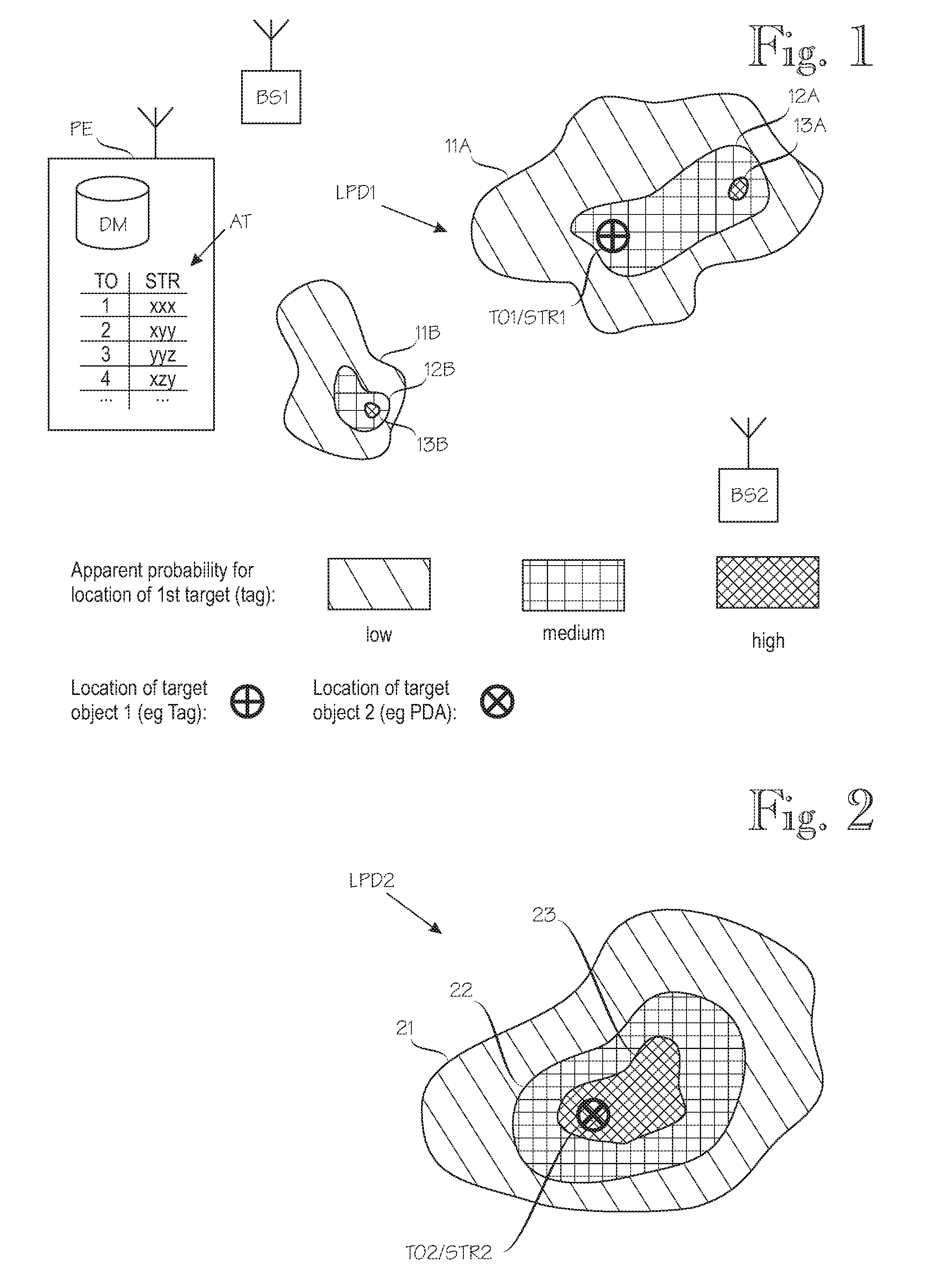
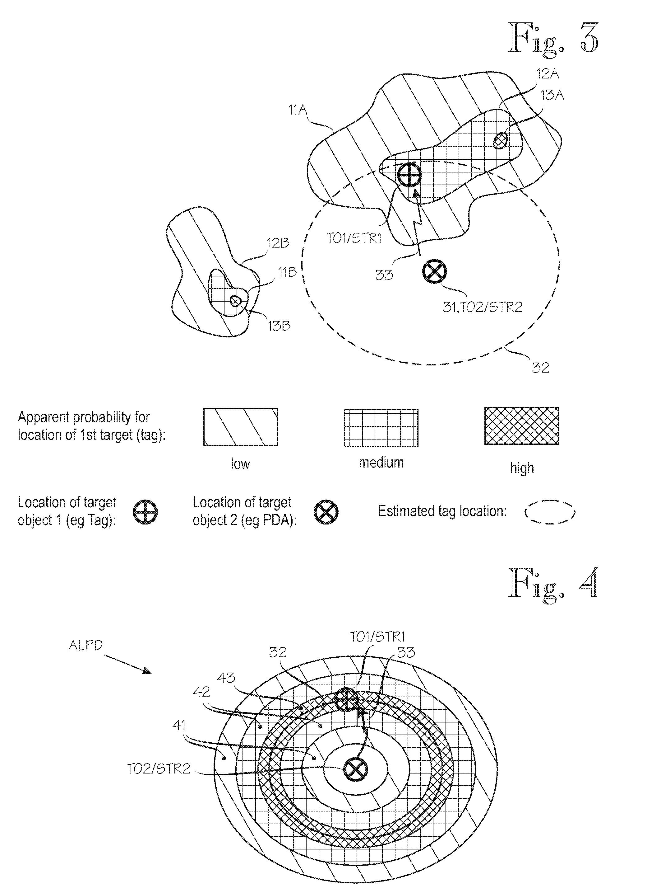
[0060]FIGS. 1 through 5 demonstrate the operating principle of the invention by means of gradually progressing schematic illustrations. In order to provide a concrete application example, FIGS. 1 through 5 are based on the assumption that the first target object is a low-cost tag which suffers from the positioning problems described in the background section of this patent specification, while the second target object is a palmtop computer or personal digital assistant (“PDA”) having more extensive signal measurement capabilities. For example, a typical PDA's battery is bigger and charged more frequently than a tag's battery, the PDA has more processing power and since it has other uses apart from positioning, it can be provided with more advanced signal processing circuitry. However, the inventive principle can be used to enhance positioning of a first target object by means of observations of a second target object even if the two target objects are equally capable, and the assump...


PUM


Abstract

Location estimation for a first target object assisted by a second target object, which have co-located signalling devices is provided. A positioning engine employs a data model of a location-dependent physical quantity and determines location probability distributions for the target objects. One signalling device sends positioning-assisting signals to the other which makes observations from it. The positioning engineuses observations on the physical quantity and the positioning-assisting signals to make a quantity observation set, and determines location probability distributions for the target objects. The positioning engine determines an updated first location probability distribution based on the location probability distributions and the positioning-assisting observation set. The positioning engine determines the location estimate for the first target object based on the updated first location probability distribution and triggers a physical action based on the location estimate for the first target object.

Description

FIELD OF THE INVENTION[0001]The invention relates generally to techniques for determining a location estimate for a first target object in an environment which also comprises a second target object and wherein at least one location-dependent physical quantity is influenced by the location of the second target object and wherein an initial location estimate for the second target object is determined based on a data model of the at least one location-dependent physical quantity and on observations on the at least one location-dependent physical quantity.BACKGROUND OF THE INVENTION[0002]An illustrative but non-restrictive application of the present invention relates to location estimation for positioning tags, or briefly “tags”. In the present context tags are electronic devices whose principal purpose is to assist estimating the location of more valuable entities co-located with the tags, such as humans or pieces of equipment.[0003]In a representative implementation the tags are opera...

Claims


Application Information

Patent Timeline
IPC IPC(8): G01S5/02
CPCG01S5/0072G01S5/0284G01S5/02G01S5/16G01S5/0252G01S5/02525
Inventor MISIKANGAS, PAULIVASKO, KARIKOUTANIEMI, ARSI
Owner AIRISTA FLOW INC
Learn More