Power converter

a power converter and converter technology, applied in the field of power converters, can solve the problems of increasing the weight and volume of the apparatus, becoming noise sources, and a big problem to solve, and achieve the effect of increasing the weight and volume of the apparatus

Active Publication Date: 2011-01-27
HITACHI LTD
View PDF8 Cites 23 Cited by
  • Summary
  • Abstract
  • Description
  • Claims
  • Application Information

AI Technical Summary

Benefits of technology

[0021]According to the invention, to suppress the noise generated by the interconnected reactor and the like of the distribution system, the power converter having a plurality of converter cells, which are configured of an IGBT and the like, cascade connected for individual phases is linked with the distribution system, and the interconnected reactor is disposed between them. At this time, the noise frequency is increased to a level not lower than the maximum frequency of the human audible range to suppress the noise generated from the above-described power converter. To do so, the frequency of an output current harmonic component which is the above-described noise source needs to exceed the maximum frequency of the human audible range. To obtain the frequency of the output current harmonic component which has exceeded the maximum frequency of the human audible range, it is adequate to determine that the frequency of a driving carrier wave for each converter cell in the power converter in which the phases of the carrier waves of the converter cells are mutually shifted by a given value between the converter cells meets the following equation (1):
where, fcarrier is the frequency of the converter cell carrier wave, faudibility<sub2>—< / sub2>max is the maximum frequency of the human audible range, and N is the number of the converter cells cascade connected for each phase.
[0022]According to the power converter of the invention, since the frequency of the output current harmonic component which was the cause of the noise exceeds the human audible range, the sound cannot be recognized by a human being, and the noise suppression can be realized as a result.

Problems solved by technology

Since the conventional power converter is hard to output a high voltage and uses the multiple transformer to link with the AC system, the whole apparatus results in increasing its weight and volume.
Especially, since the power converter is mounted on a power pole when it is used for power distribution, the increase in weight and volume of the apparatus is a big issue to be solved.
Since this reactor is directly connected to the distribution system through an electric cable, the same vibration is propagated to a distribution line, a power pole and others, which also become noise sources.
In a case where the reactor is used for electric power distribution, it is installed in a residential area, so that noise generation is a particularly serious problem, and the above-described noise reduction was a big technical object.

Method used


Image

  • Power converter
  • Power converter
  • Power converter

Examples


embodiment 1

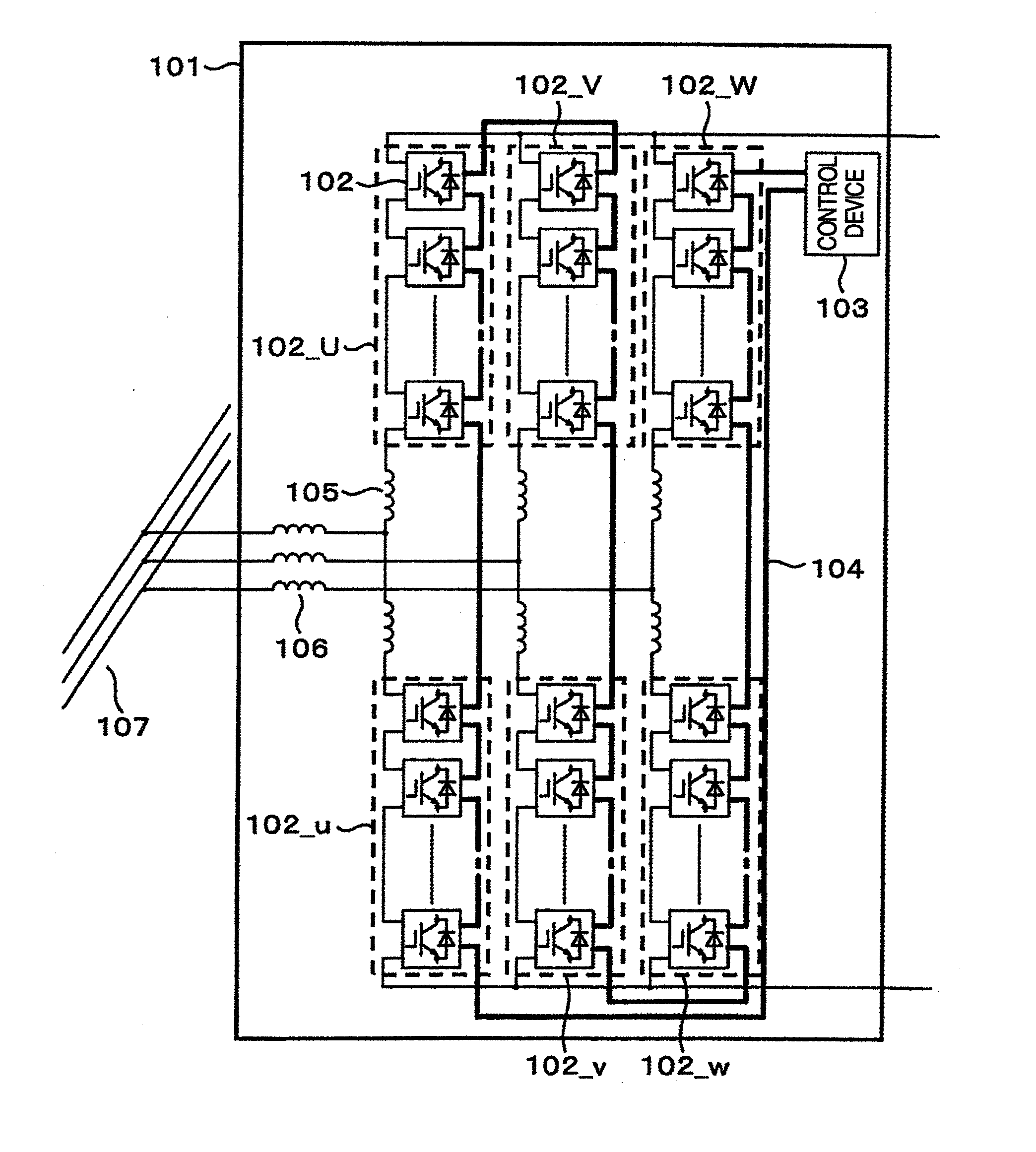
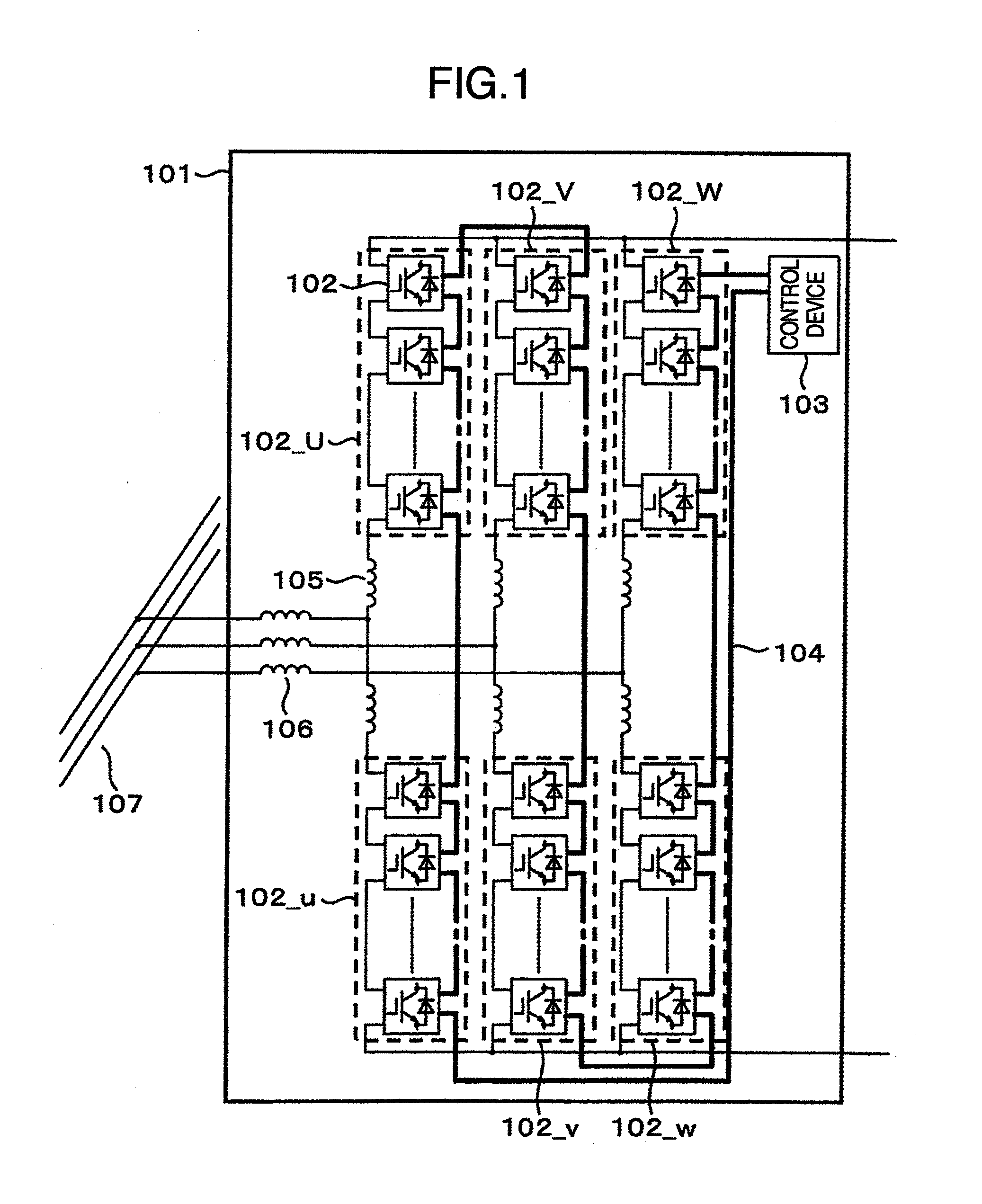
[0046]FIG. 1 is a configuration view of a power converter having converter cells cascade connected and in a state linked with a system 107 according to one embodiment of the invention. A power converter 101 comprises converter cells 102, a control device 103, a signal line 104 for transmitting control signals from the control device 103 to the individual converter cells, buffer reactors 105, and interconnected reactors 106. In the drawing, 102_U, 102_V, 102_W, 102—u, 102—v and 102—w have the plural converter cells 102 connected in cascade and are defined as arms. Thus, the upper arms 102_U, 102_V and 102_W are called a U-phase positive side arm, a V-phase positive side arm and a W-phase positive side arm, and the lower arms 102—u, 102—v and 102—w are called a U-phase negative side arm, a V-phase negative side arm and a W-phase negative side arm. And, the converter cells 102 and the control device 103 are connected in a row by the signal line 104 as shown in FIG. 1.

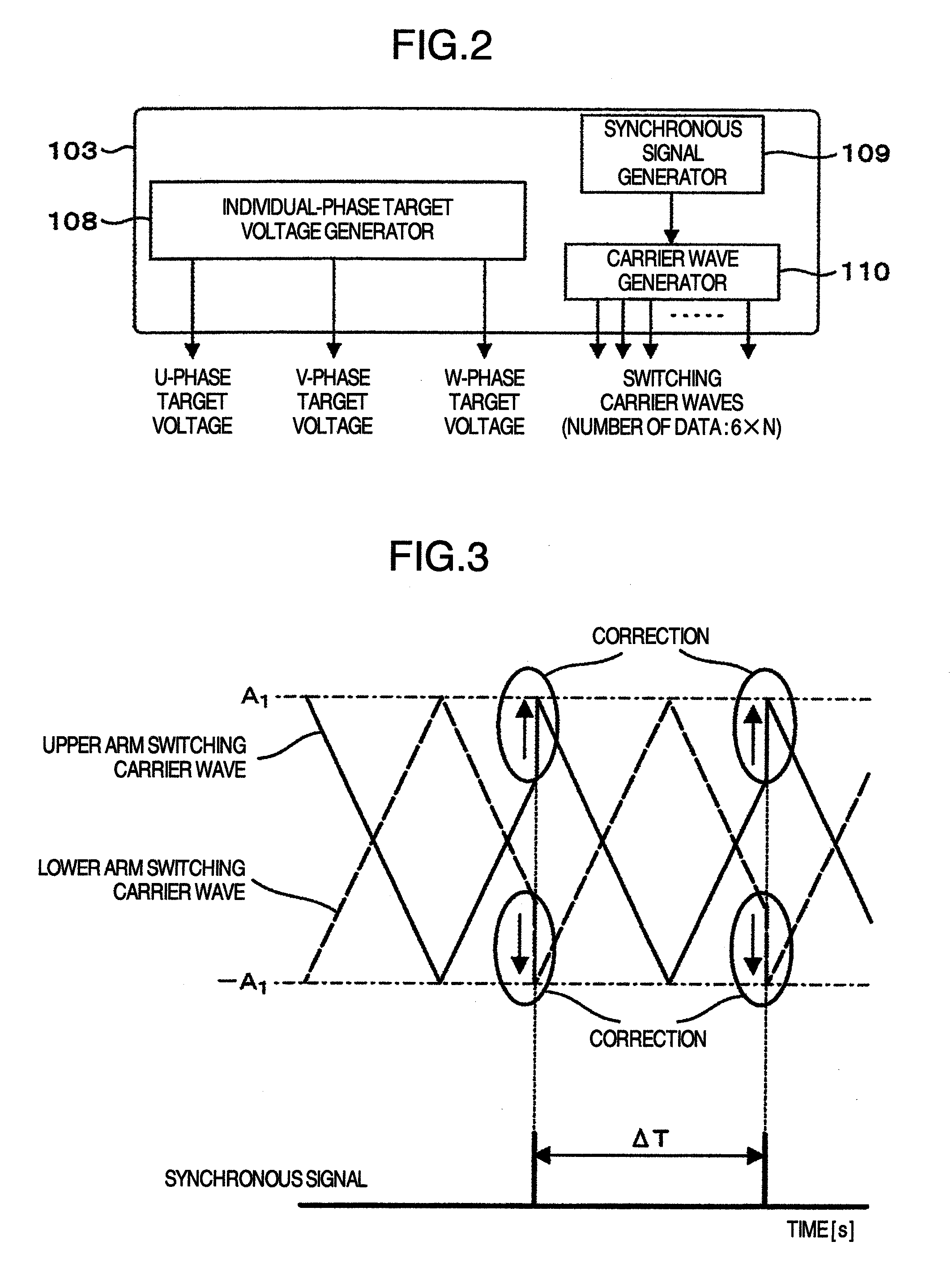
[0047]FIG. 2 shows...

embodiment 2

[0055]In Embodiment 1 described above, the converter cells 102 are configured of a so-called half bridge type circuit as shown in FIG. 4, but they may be configured of a full bridge type circuit as shown in FIG. 9. In the drawing, 111_A designates an IGBT element 111a and an IGBT element 111b, and 111_B designates an IGBT element 111c and an IGBT element 111d. When 111_A and 111_B are defined as legs respectively, the converter cell 102 in this embodiment is configured of a cell 114, which comprises the legs 111_A and 111_B each having two IGBT elements 111, a DC capacitor 112 and four fuses 113, a converter cell control circuit 115, a gate driver 116, a self-feeding supply 117 and a gate power supply 118.

[0056]FIG. 10 shows a schematic configuration view of the control device 103 in this embodiment. In the full bridge type circuit of this embodiment, the above-described legs 111_A and 111_B control the switching operation according to two types of target voltages which are called a...

embodiment 3

[0059]In Embodiments 1 and 2, the outputs of the control device 103 are the target voltages of each of the U-phase, the V-phase and the W-phase and the carrier waves of the converter cells but may be individual-phase target voltages and synchronous signals.

[0060]FIG. 13 shows a schematic configuration view of the control device 103 when the converter cell 102 is configured of a half bridge type circuit, and FIG. 14 shows a schematic configuration view of the converter cell control circuit 115. In this embodiment, the synchronous signal is outputted to the appropriate converter cell control circuit 115 at the every given time ΔT. And, in the converter cell control circuit 115, the carrier wave outputted from the carrier wave generator 110, which forcefully corrects a value by the synchronous signal inputted at every cycle ΔT, is compared with the target voltage outputted from the control device 103 for the magnitude by the comparator 119, and the ON / OFF signal is outputted to the gat...


PUM


Abstract

The noise generated from a power converter is suppressed by increasing the noise frequency to a level not lower than the maximum frequency of the human audible range. To obtain the frequency of an output current harmonic component as a noise source which has exceeded the maximum frequency of the human audible range, it is adequate to determine that the frequency of a driving carrier wave for the individual converter cells in the power converter, in which the phases of the carrier wave for the converter cells are mutually shifted by a given value between the converter cells, meets the following equation.fcarrier≧faudibility<sub2>—< / sub2>max÷N

Description

CROSS-REFERENCE TO RELATED APPLICATION[0001]The present invention is related to PCT application No. PCT / JP2010 / 052833 filed on Feb. 24, 2010, claiming the invention priority based on Japanese Patent Application No. 2009-080856, filed on Mar. 30, 2009.BACKGROUND OF THE INVENTION[0002]The present invention relates to a power converter which has converter cells configured by cascade connection, and more particularly to a power converter which suppresses a problem resulting from output current harmonics.[0003]A conventional power converter has a multiple transformer to increase the output voltage to a high level and it is linked with an AC system. Since the multiple transformers are large in weight and volume, the whole apparatus has a large weight and volume as a result.SUMMARY OF THE INVENTION[0004]Since the conventional power converter is hard to output a high voltage and uses the multiple transformer to link with the AC system, the whole apparatus results in increasing its weight an...

Claims


Application Information

Patent Timeline
Patent Type & Authority Applications(United States)
IPC IPC(8): H02M7/04
CPCH02M1/14H02M7/219H02M2001/0006H02M2007/4835H02M7/5395H02M7/483H02M1/0006H02M7/4835H02M1/0043
Inventor YAMADA, YOICHIROKATOH, SHUJIINOUE, SHIGENORI
Owner HITACHI LTD
Why Eureka
Try Eureka