Communication system, reception device, and communication method
Active Publication Date: 2011-01-27
SHARP KK
View PDF5 Cites 5 Cited by
Summary
Abstract
Description
Claims
Application Information
AI Technical Summary
This helps you quickly interpret patents by identifying the three key elements:
Problems solved by technology
Method used
Benefits of technology
Benefits of technology
[0031]The communication system, the reception device, and the communication method of the present invention can obtain good transmission characteristics between the transmission device and the reception device without increasing the number of reception antennas of the reception device.
Problems solved by technology
However, if the radio reception device 52 is a small-size radio reception device, there is a problem in that it is difficult to increase the number of reception antennas since the number of reception antennas capable of being mounted is limited.
Method used
Image
Click on the blue label to locate the original text in one second.
Reading with bidirectional positioning of images and text.
Examples
first embodiment
[0044]First, a communication system according to the first embodiment of the present invention will be described. The communication system includes a radio transmission device 100 (FIG. 1) and a radio reception device 200 (FIG. 2). In the first embodiment, the case where MIMO-orthogonal frequency division multiplexing (OFDM) is used will be described.
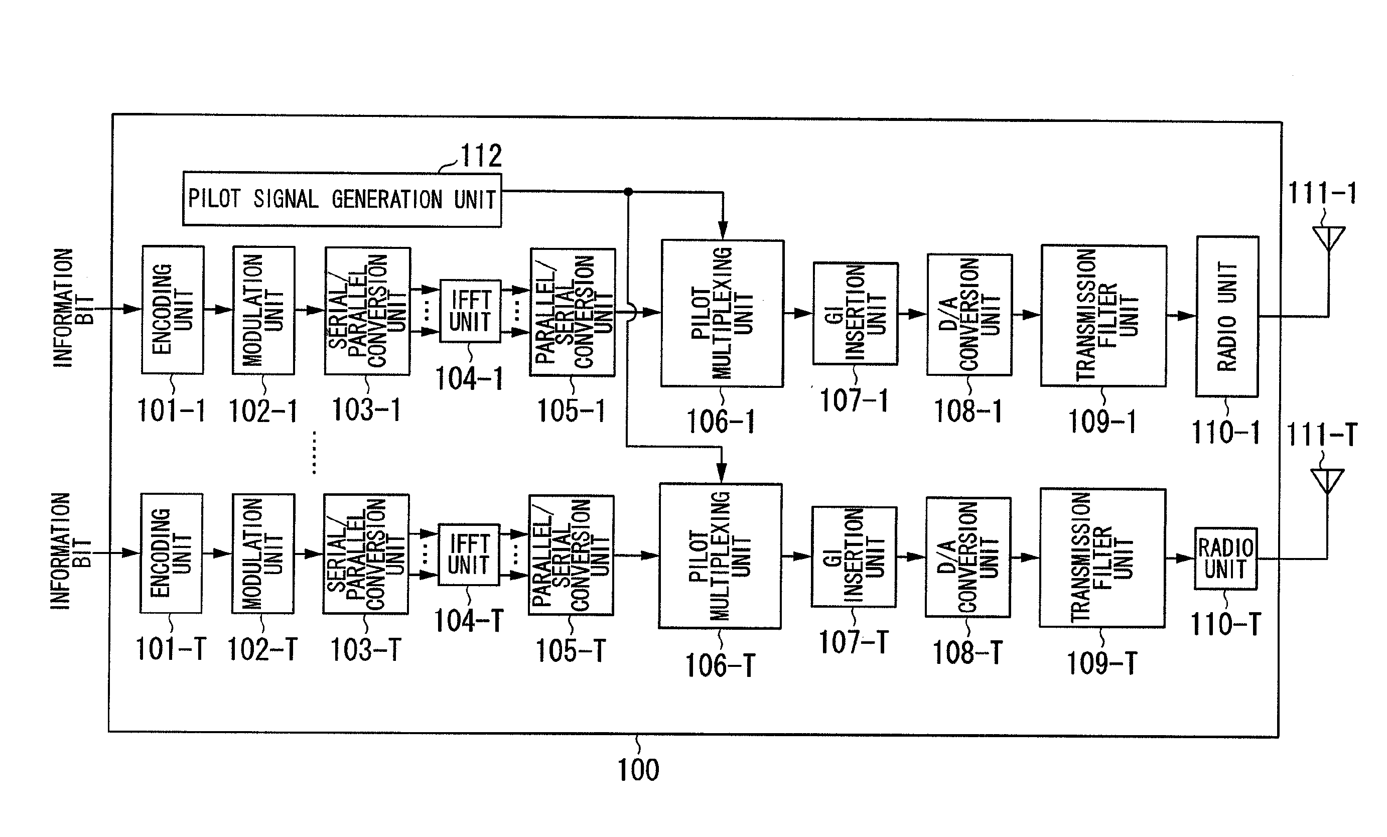
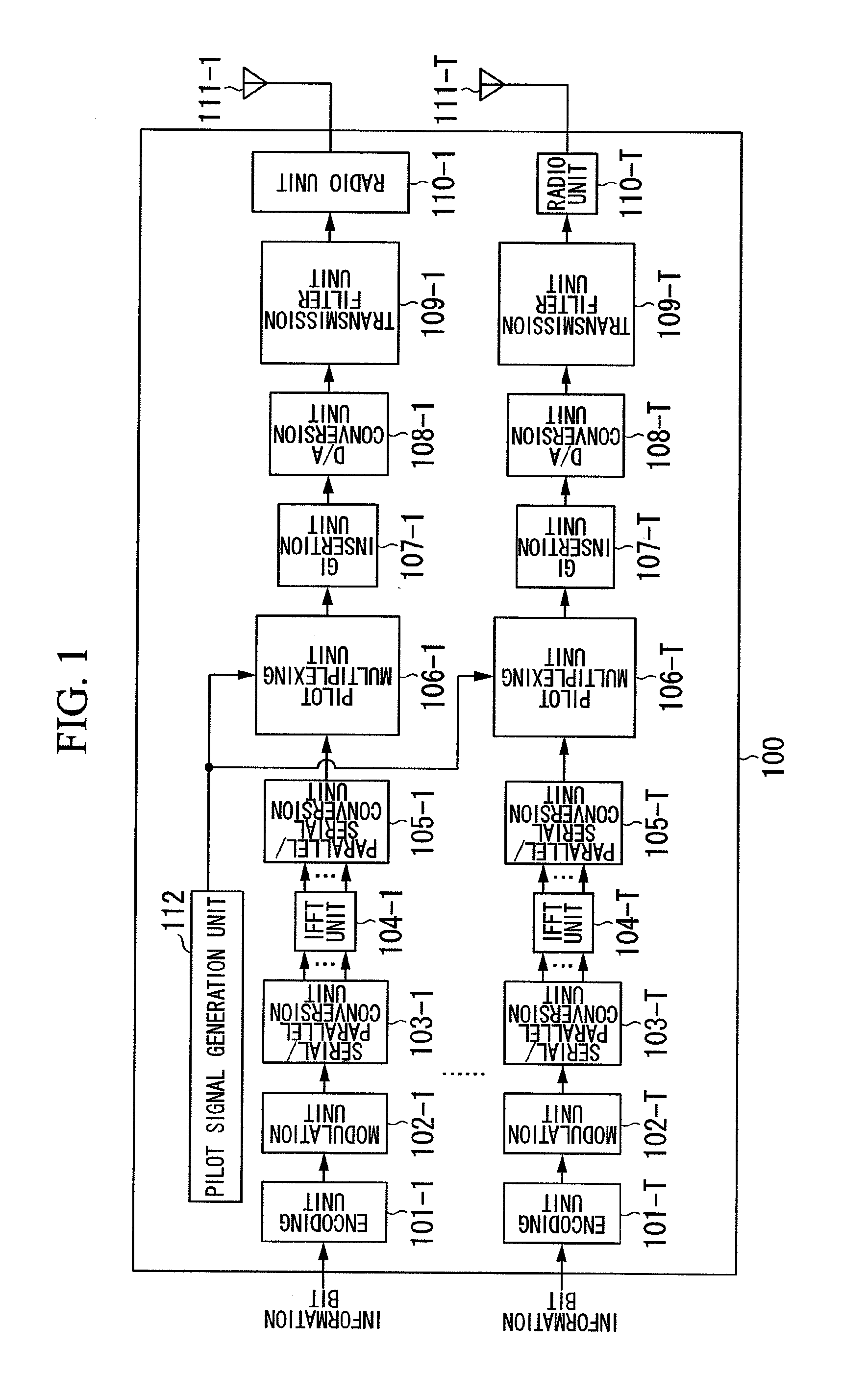
[0045]FIG. 1 is a schematicblock diagram showing the configuration of the radio transmission device 100 according to the first embodiment of the present invention. The radio transmission device 100 includes encoding units 101-1 to 101-T (T is an integer greater than or equal to 2), modulation units 102-1 to 102-T, serial / parallel conversion units 103-1 to 103-T, IFFT (inverse fast Fourier transform) units 104-1 to 104-T, parallel / serial conversion units 105-1 to 105-T, pilotmultiplexing units 106-1 to 106-T, GI (guard interval) insertion units 107-1 to 107-T, D / A (digital to analogue) conversion units 108-1 to 108-T, transmission filt...
second embodiment
[0125]Next, a communication system according to the second embodiment of the present invention will be described. This communication system includes a radio transmission device 100 and a radio reception device 600. In the second embodiment, the case of using a MIMO-parallel interference cancel (PIC) will be described.
[0126]Since the radio transmission device 100 according to the second embodiment is the same as the radio transmission device 100 described with reference to FIG. 1 of the first embodiment, description thereof is omitted.
[0127]FIG. 6 is a schematicblock diagram showing the configuration of the radio reception device 600 according to the second embodiment of the present invention. The radio reception device 600 includes reception antennas 601-1 to 601-R, radio units 602-1 to 602-R, reception filter units 603-1 to 603-R, A / D conversion units 604-1 to 604-R, block division units 605-1 to 605-R, a propagation channel estimation unit 606, a signal detection unit 607, and a ...
third embodiment
[0151]Next, a communication system according to the third embodiment of the present invention will be described. This communication system includes a radio transmission device 800 and a radio reception device 900. In the third embodiment, the case of using a MIMO-multi carrier-code division multiple access (MC-CDMA) will be described.
[0152]In MC-CDMA for spreading in a frequency domain, multi-code interference (MCI) occurs because of frequency selectivityfading. Since MCI degrades the performance of reception, the performance of a block division process is also degraded. In the third embodiment, the case of combining an MCI canceller which cancels MCI with the block division process will be described.
[0153]FIG. 8 is a schematicblock diagram showing the configuration of the radio transmission device 800 according to the third embodiment of the present invention. The radio transmission device 800 includes code channel signal generation units 801-1-1 to 801-Cn-1, . . . , and 801-1-T ...
PUM
Abstract
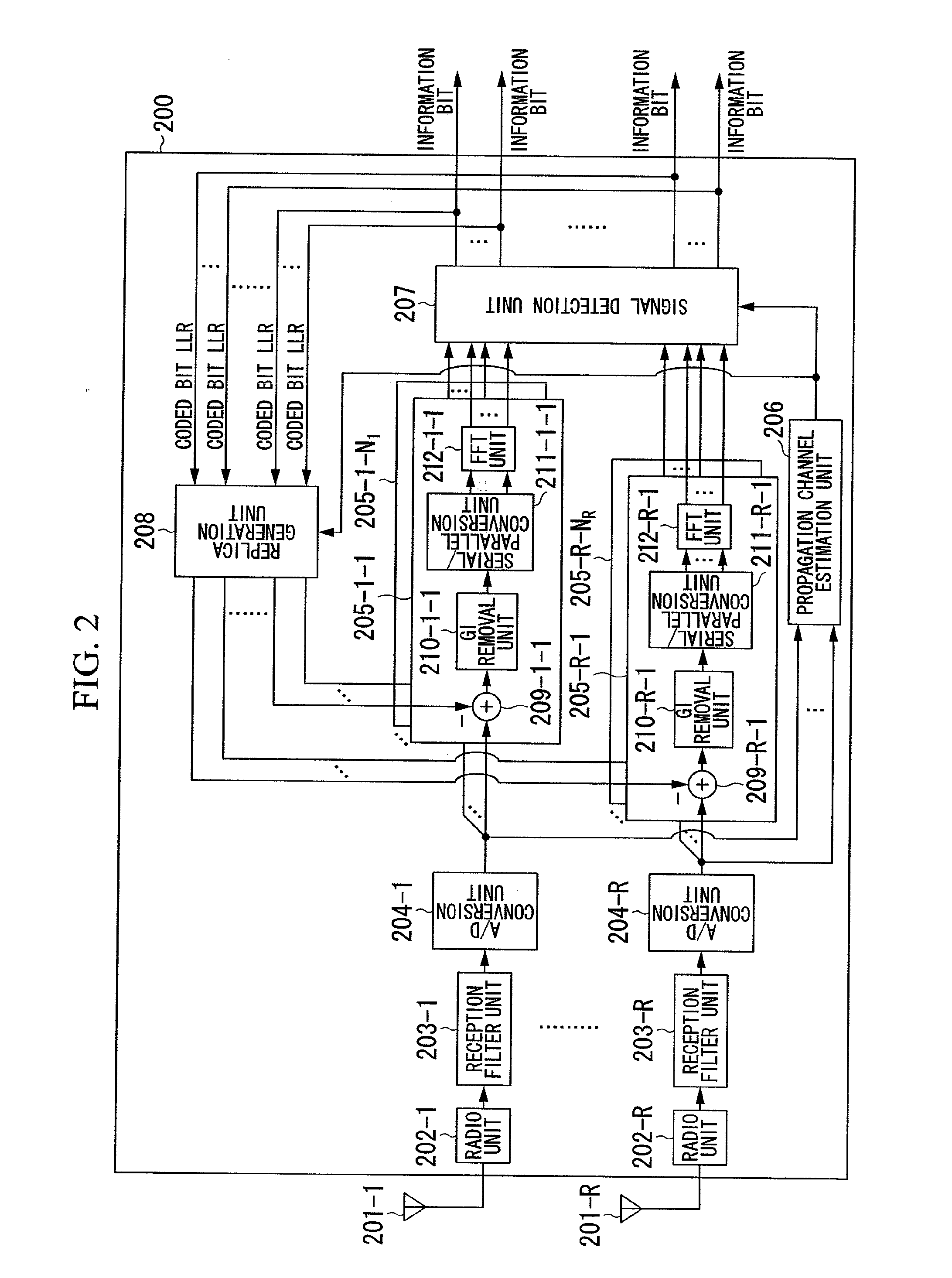
A reception device which communicates with a transmission device including multiple transmission antennas, the reception device including: at least one reception antenna which receives multiple transmission signals transmitted by the transmission device from the multiple transmission antennas; a propagation channel response estimation unit which estimates propagation channel responses among the multiple transmission antennas and the reception antenna; a block division unit which divides a reception signal of at least one of the reception antennas into multiple blocks based on a multipath; and a transmission signal detection unit which detects the transmission signals transmitted by the transmission device based on the reception signal divided by the block division unit into the multiple blocks and the propagation channel responses estimated by the propagation channel response estimation unit. The transmission signal detection unit includes: an interference cancellation unit which generates and removes an interference replica; and a signal separation unit which separates a signal into which a transmission signal is multiplexed from an output of the interference cancellation unit.
Description
TECHNICAL FIELD[0001]The present invention relates to a communication system, a reception device, and a communication method.[0002]This application claims priority to and the benefits of Japanese Patent Application No. 2008-119287 filed on Apr. 30, 2008, the disclosure of which is incorporated herein by reference.BACKGROUND ART[0003]Recently, in the field of wireless communication, multiple input multiple output (MIMO) systems which transmit multiple independent transmission signals from a radio transmission device to a radio reception device at the same frequency and timing so as to implement high speed transmission have been attracting attention. MIMO may increase the transmission rate without increasing the frequency bandwidth.[0004]In the MIMO systems, different transmission signals are multiplexed and received by a radio reception device. Thus, technology for separating spatially multiplexed transmission signals is necessary for the radio reception device.[0005]FIG. 12 is a sch...
Claims
Application Information
Patent Timeline
Application Date:The date an application was filed.
Publication Date:The date a patent or application was officially published.
First Publication Date:The earliest publication date of a patent with the same application number.
Issue Date:Publication date of the patent grant document.
PCT Entry Date:The Entry date of PCT National Phase.
Estimated Expiry Date:The statutory expiry date of a patent right according to the Patent Law, and it is the longest term of protection that the patent right can achieve without the termination of the patent right due to other reasons(Term extension factor has been taken into account ).
Invalid Date:Actual expiry date is based on effective date or publication date of legal transaction data of invalid patent.

