Rotation drive controlling system for construction machine

Active Publication Date: 2011-01-27
KOMATSU LTD
View PDF18 Cites 20 Cited by
  • Summary
  • Abstract
  • Description
  • Claims
  • Application Information

AI Technical Summary

Benefits of technology

[0037]In the swing drive controlling system of a construction machine according to the above aspect of the invention, useless consumption of the discharge flow discharged from a hydraulic pump that is controlled to provide a preset pump absorption torque according to the pump discharge pressure of the hydraulic pump or from an electronic pump of which pump displacement can be directly designated by an electric signal can be reduced. Further, in the aspect of the invention, substantially the same operability in swinging the upper structure as that without reducing the discharge flow rate as in the aspect of the invention can be provided.
[0038]Specifically, when the pump discharge pressure of the hydraulic pump exceeds the first set value while operating the swing control lever, the value of the target pump displacement for controlling the pump displacement of the hydraulic pump can be reduced by the adjustment by the adjuster in accordance with the pump discharge pressure. Thus, the flow discharged without being used for driving the hydraulic swing motor can be reduced substantially without changing the pump discharge flow for driving the hydraulic swing motor.
[0039]Further, when the pump discharge pressure falls below the second set value that is higher than the first set value, the adjustment conducted by the adjuster for reducing the value of the target pump displacement in accordance with the pump discharge pressure is canceled by the c

Problems solved by technology

However, since an inertial force for keeping the upper structure at halt is large, it takes some time before the upper structure is accelerated from the halted state to a steady swing velocity (a state at which all of the pump discharge amount commanded by the swing contr

Method used


Image

  • Rotation drive controlling system for construction machine
  • Rotation drive controlling system for construction machine
  • Rotation drive controlling system for construction machine

Examples


embodiment (

Embodiment(s)

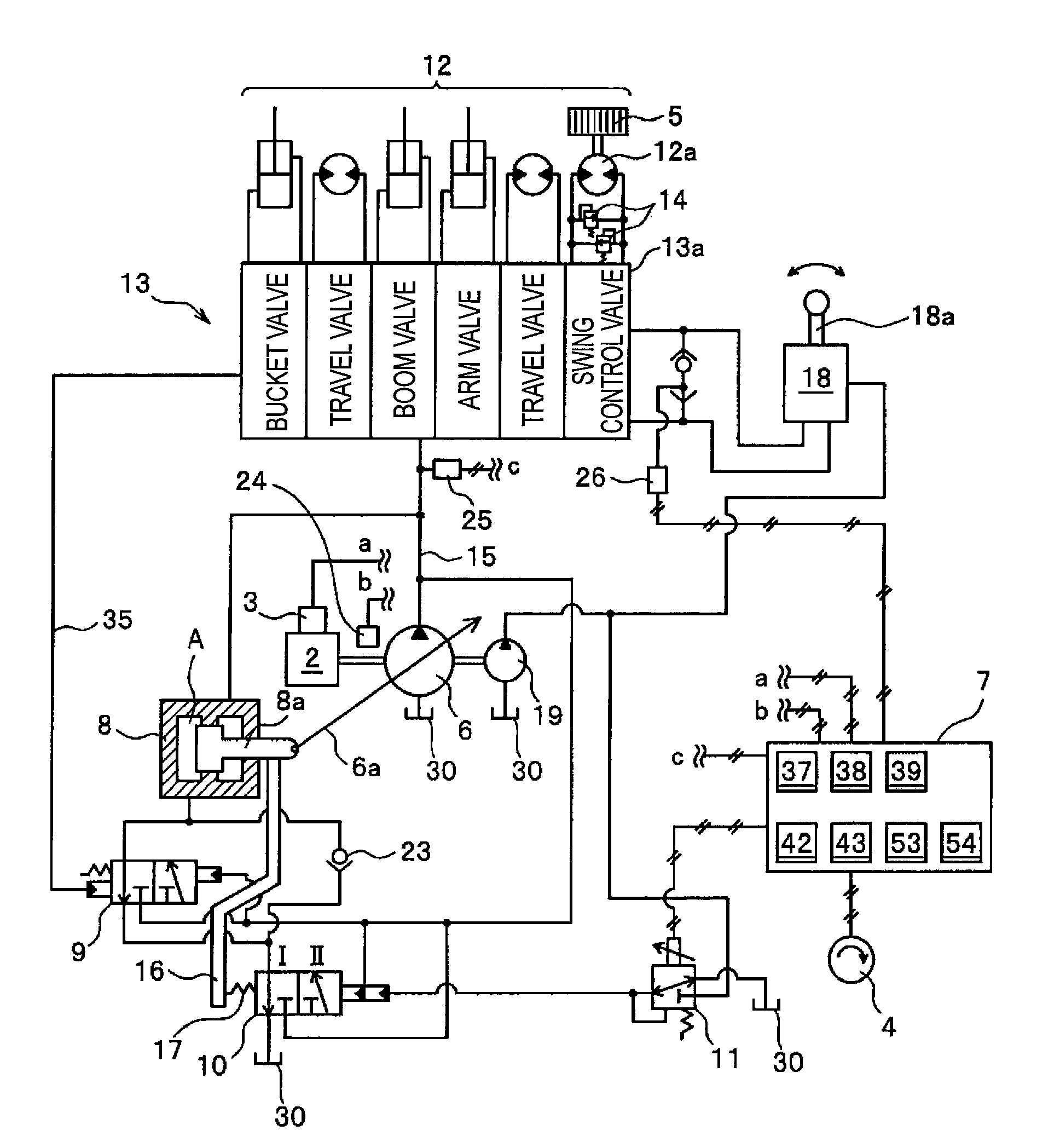
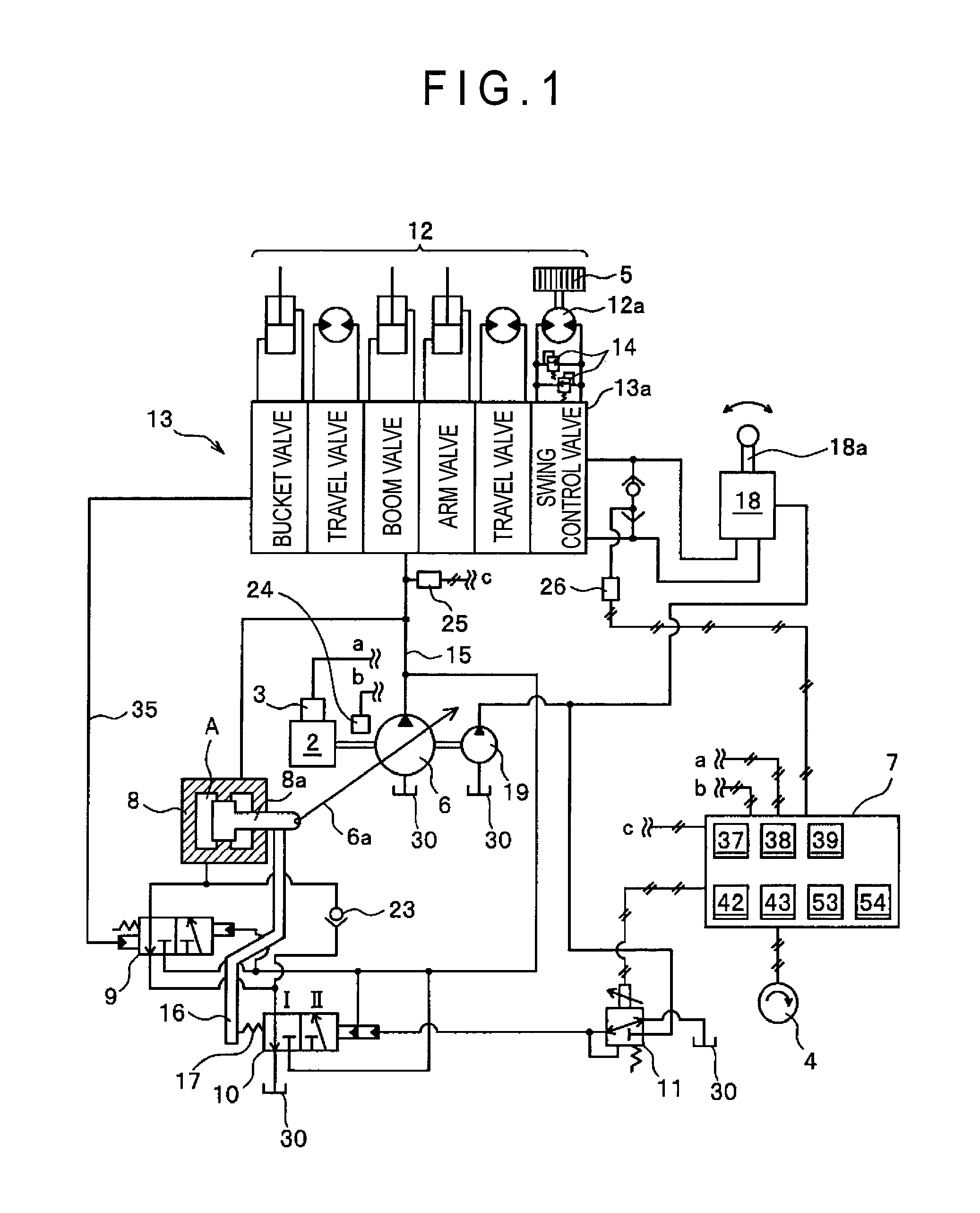
[0151]FIG. 1 shows a hydraulic circuit of the swing, drive controlling system for a construction machine according to an exemplary embodiment of the invention, which specifically shows a hydraulic circuit of the swing drive controlling system for an upper structure including a hydraulic swing motor for rotating the upper structure and a variable displacement hydraulic pump. An engine 2 is a diesel engine, of which engine torque is controlled by adjusting an amount of fuel injected into a cylinder of the engine 2. The fuel adjustment can be conducted by a conventionally known fuel injector 3.

[0152]A variable displacement hydraulic pump 6 (referred to as a hydraulic pump 6 hereinafter) and a pilot hydraulic pump 19 are connected to an output shaft of the engine 2. The output shaft of the engine 2 is rotated to drive the hydraulic pump 6 and the pilot hydraulic pump 19. A tilt angle of a swash plate 6a of the hydraulic pump 6 is controlled by a control cylinder 8. The tilt...


PUM


Abstract

The system includes: a variable displacement hydraulic pump supplying pressure oil to a hydraulic actuator; a pressure detector detecting a pump discharge pressure from the hydraulic pump; a control valve controlling a supply of the pressure oil to the hydraulic actuator; a controller controlling a pump displacement of the hydraulic pump; a hydraulic motor rotating an upper structure of the construction machine; a swing relief valve defining a relief pressure of the hydraulic motor; and a control lever switching a control valve for the hydraulic motor. The controller includes: an adjuster that, when a pump discharge pressure detected by the pressure detector exceeds a first set value, conducts an adjustment to reduce the pump displacement; and a canceller that cancels the adjustment when the pump discharge pressure falls below a second set value. The second set value is equal to or larger than the first set value.

Description

TECHNICAL FIELD [0001]The present invention relates to a swing drive controlling system for a construction machine for driving a hydraulic swing motor for rotating an upper structure of a construction machine while controlling a relief flow rate discharged without being used for driving the hydraulic swing motor.BACKGROUND ART [0002]In a top-swinging construction machine such as a hydraulic excavator, an upper structure is swingably attached to a lower vehicle body (base carrier) provided with a carrier. A working equipment including a boom, an arm, a bucket or the like is pivotally mounted to the upper structure. The base carrier is driven by a travel hydraulic motor while the upper structure is swung by a hydraulic swing motor. The boom, arm, bucket and the like are pivoted respectively by a boom cylinder, an arm cylinder, a bucket cylinder and the like.[0003]Pressure oil discharged from a variable displacement hydraulic pump driven by an engine is supplied to or discharged from h...

Claims


Application Information

Patent Timeline
IPC IPC(8): F04B49/00
CPCE02F9/123F15B2211/7058E02F9/2285E02F9/2296F15B11/055F15B2211/20546F15B2211/26F15B2211/3052F15B2211/3116F15B2211/31576F15B2211/329F15B2211/50518F15B2211/6309F15B2211/6316F15B2211/6333F15B2211/6346E02F9/2235
Inventor AKIYAMA, TERUOASADA, HISASHIKITAJIMA, JINMARUTA, KAZUHIROOOI, TAKESHIICHIHARA, MASASHI
Owner KOMATSU LTD
Why Eureka
Try Eureka