Apparatus and method for treating formed parts by means of high-energy electron beams

a technology of electron beams and apparatuses, applied in the field of apparatuses and a method for treating formed parts by means of high-energy electron beams, can solve the problems of relatively large time and equipment expenditure, high technological effort and expense, and other problems, to achieve the effect of reducing time or technology expenditure and reducing productivity disadvantages

Inactive Publication Date: 2011-01-27
ROBERT BOSCH GMBH
View PDF4 Cites 11 Cited by
  • Summary
  • Abstract
  • Description
  • Claims
  • Application Information

AI Technical Summary

Benefits of technology

[0018]This device is for example a gripper that is controllable in a plurality of degrees of freedom, which is preferably equipped with an inflatable and / or electromagnetic gripper element. Because of the proposed gripper mechanism and because the formed parts are placed upright, an offset that virtually predetermines the labyrinth required for the shielding is automatically created in the conduit, the conduit being angled for that purpose. The X-radiation generated in the treatment zone of the processing chamber is thus shielded or reflected to the inlet and outlet; this makes a very compact structure with very robust mechanics possible, and makes other, otherwise necessary, complicated constructions for the conduit, tunnel or gate superfluous.
[0021]With the aid of so-called “paddles”, for instance, as controllable baffles in the processing chamber, the air pressure control proposed here in the conduit is advantageous above all because the formed parts to be treated are not a hose but discrete objects with a defined spacing from one another, and the air flowing along the formed parts thus experiences fluctuations at the constrictions and interfaces with the surroundings, and these fluctuations are expressed in pressure fluctuations. To compensate for these fluctuations, the paddle can be used in such a way that the flow cross section is artificially reduced whenever the air could too easily flow out into adjoining regions and thus would lower the pressure.
[0028]A further advantageous embodiment contains a chamber, partitioned off by a lead-coated bulkhead, in the outlet region, which chamber is capable of holding at least one formed part that can be removed from outside via a further bulkhead or a door. This chamber is ideally disposed perpendicular to the outlet conveyor belt, and with the bulkhead open, the formed part can be pushed over into the chamber by means of a translational motion perpendicular to the outlet direction. After closure of the bulkhead, the formed part can then be removed via the outer door, without having to interrupt the irradiation operation. In an especially advantageous embodiment, the outer door comprises a double-lidded gate, with which sterile removal of the formed part is possible.
[0030]The invention therefore advantageously solves a series of technical problems and makes it possible to create both an apparatus with a cyclically operating transporting device and a method which overcome the disadvantages of the prior art in treatment with electron beams. In particular, the apparatus and the method are suitable for modifying properties of three-dimensional formed parts, with little expenditure of time or technology, in such a way that a sufficiently uniform modification of the entire surface or of the peripheral regions of the formed parts is attained and nevertheless, no productivity-limiting disadvantages result from the overall arrangement of the electron accelerators.

Problems solved by technology

A disadvantage of this is that it involves relatively great expenditure in terms of time and equipment.
With such apparatuses, although the time expenditure is reduced compared to other known embodiments in which a formed part is subjected to electrons in a plurality of passes, the technological effort and expense are nevertheless very high, because three electron accelerators are used.
If the material use temperature were exceeded, the vulnerable material of the window covering would otherwise be destroyed by the mechanical strain from the externally applied atmospheric pressure in comparison to the high vacuum in the interior of the beam generator.
In that case, a considerable proportion of energy strikes the absorber, which limits the projection of additional energy onto the opposite electron discharge window.
With the known devices, depending on the geometry of the formed parts to be treated, in individual surface regions overdose factors are attained that are unacceptable for many applications for achieving adequately uniform properties over the entire surface.

Method used


Image

  • Apparatus and method for treating formed parts by means of high-energy electron beams
  • Apparatus and method for treating formed parts by means of high-energy electron beams

Examples


Embodiment Construction

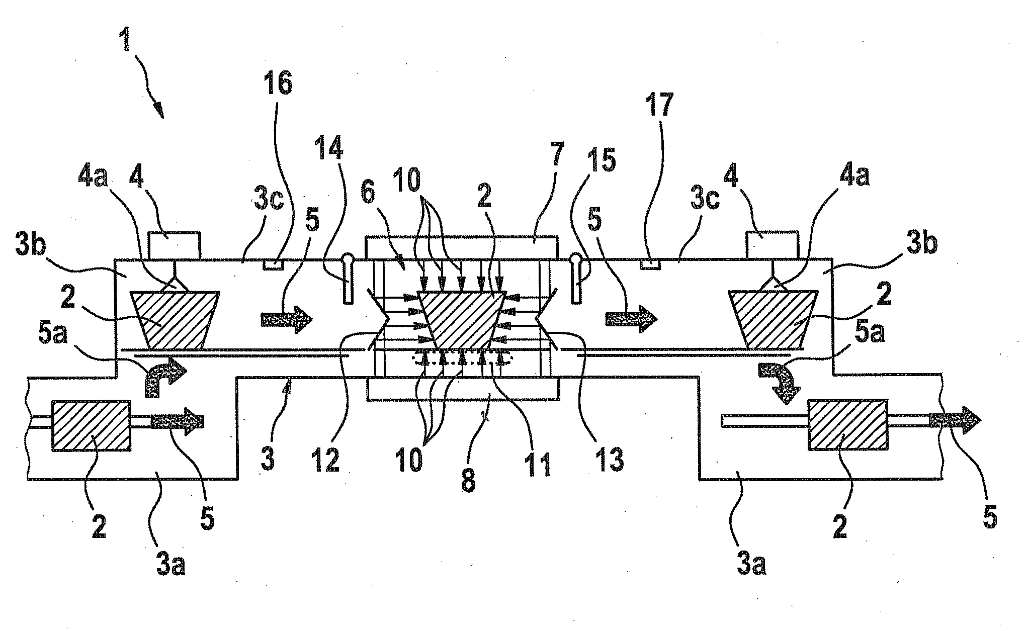
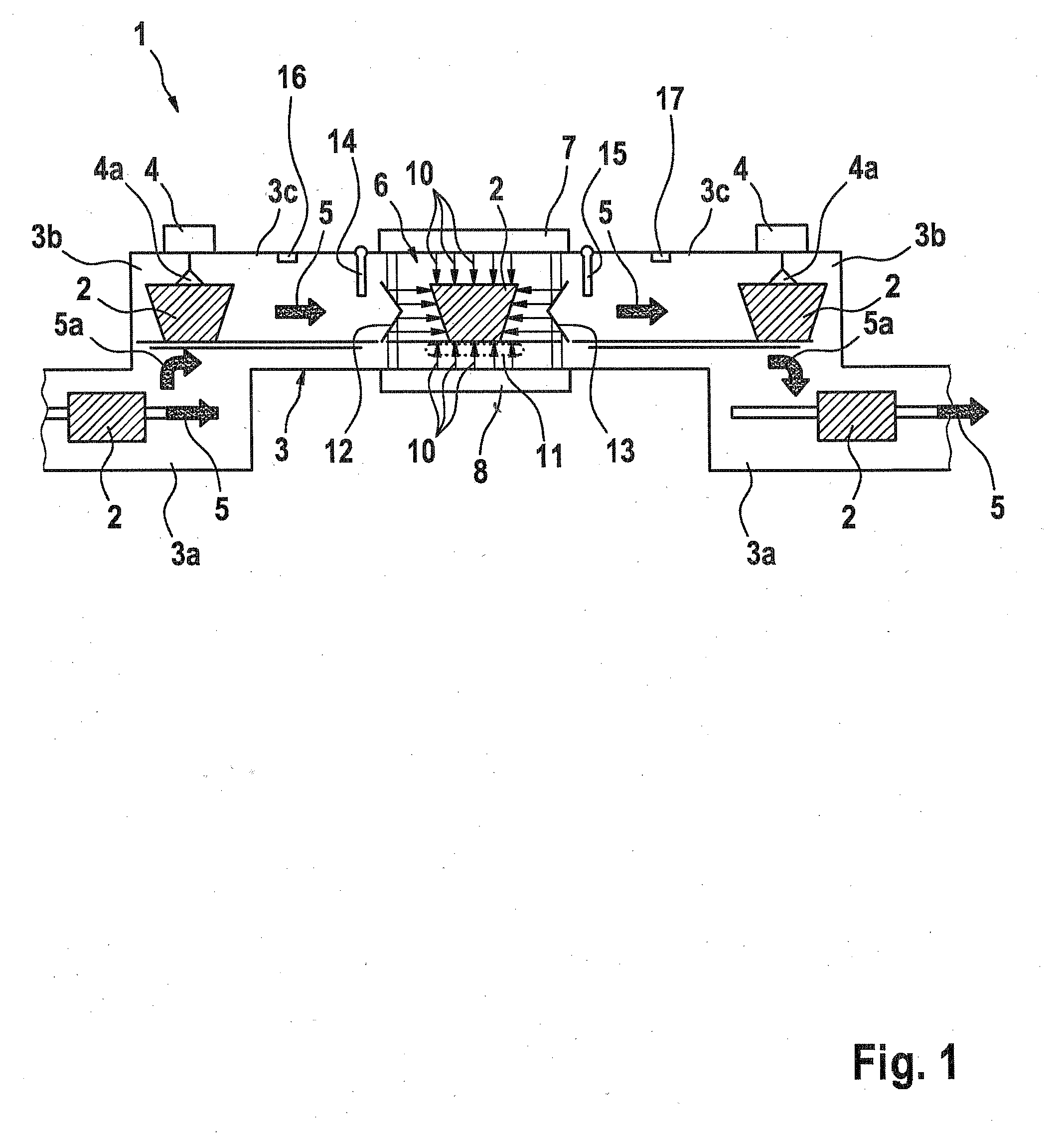
[0033]In FIG. 1, an apparatus 1 for electron treatment for the sake of sterilizing the surface of a formed part 2 is shown in a top view on the transporting plane in a conduit 3. The formed part 2 here is a three-dimensional object of rectangular shape in top view, as can be seen from the conduit portions 3a at the inlet and at the outlet.

[0034]One gripper 4 is disposed in each conduit portion 3b; under suitable control and having with a gripper element 4a, it puts the formed part 2 into an upright position, so that a trapezoidal cross section of the formed part 2 in the conduit portions 3c can now be seen. Arrows 5 indicate the transporting direction for the formed parts 2, and arrows 5a are intended to symbolically illustrate the rotation from the horizontal to an upright position of the formed part 2.

[0035]A processing chamber 6 is present here as a treatment zone for the formed parts 2; it is defined by two parallel, opposed electron discharge windows 7 and 8, extending vertical...


PUM

PropertyMeasurementUnit
temperatureaaaaaaaaaa
surface areaaaaaaaaaaa
degrees of freedomaaaaaaaaaa

Abstract

The invention relates to a device for treating formed parts with high-energy electron beams. The electron beams are guided by two opposite stationary or displaceable electron discharge windows onto the formed part and bounding a process space for the formed part. A transport device is present for the formed part, by which the formed part can be guided through the process space to the electron discharge windows disposed substantially vertically perpendicular to the transport direction. A channel is disposed in the process space for transporting the formed part and largely shielded against the X-ray radiation.

Description

PRIOR ART[0001]The invention relates to an apparatus and a method for treating formed parts by means of high-energy electron beams, and in particular also for modifying material properties of the surface and in the peripheral region of three-dimensional formed parts as generically defined by the preamble to the apparatus claim and method claim.[0002]From International Patent Disclosure WO 2007 / 107331 A1, it is already known that a three-dimensional formed part is treated by means of electrons and in the process comes to rest between two electron discharge windows, on at least one of which an electron accelerator is disposed. Reflectors are also disposed here in such a way that particularly in lateral regions of the formed part that might be subjected to electrons inadequately, for instance because of shading, the electrons are directed in particular from the lateral regions onto the formed part.[0003]From German Patent DE 40 28 479 C2, it is also known that for near-surface heat tre...

Claims


Application Information

Patent Timeline
Patent Type & Authority Applications(United States)
IPC IPC(8): A61L2/00G21G5/00
CPCA61L2/087A61L2202/122H01J33/00B29C2035/0877G21K5/10B29C71/04
Inventor RAUSCHNABEL, JOHANNESEBERT, STEFFENULLMANN, OLIVERSCHMIEG, REINHOLD
Owner ROBERT BOSCH GMBH
Why Eureka
Try Eureka