Coating structure and surface processing method

a technology of coating structure and surface processing method, which is applied in the direction of superimposed coating process, light and heating apparatus, machines/engines, etc., can solve the problems of high temperature components, inability to sprayed particles, and difficulty in ensuring heat resistance and water vapor wall thinning resistance,

Inactive Publication Date: 2011-01-27
IHI CORP
View PDF12 Cites 5 Cited by
  • Summary
  • Abstract
  • Description
  • Claims
  • Application Information

AI Technical Summary

Benefits of technology

[0009]With that, it is an object of the present invention to provide anew a coating structure and a surface processing method affording to solve such an issue.

Problems solved by technology

However, intermediate layers formed by a spraying have unstable particles of ceramics (sprayed particles) therein.
For this reason, in high temperature components used under high temperature gas environments of 900 degrees C. or more, intermediate layers had tendencies to crack or get detached, so such high temperature components have been subject to a difficulty in ensuring heat resistance and water vapor wall-thinning resistance over a long service.
That is, as an issue in implementing a coating structure, or in other words, in implementing a surface processing to be convenient with ease and certainty, there has been a difficulty for high temperature components in use under high temperature gas environments of 900 degrees C. or more to have a combination of heat resistance and water vapor wall-thinning resistance secured over a long service.

Method used


Image

  • Coating structure and surface processing method
  • Coating structure and surface processing method
  • Coating structure and surface processing method

Examples


Embodiment Construction

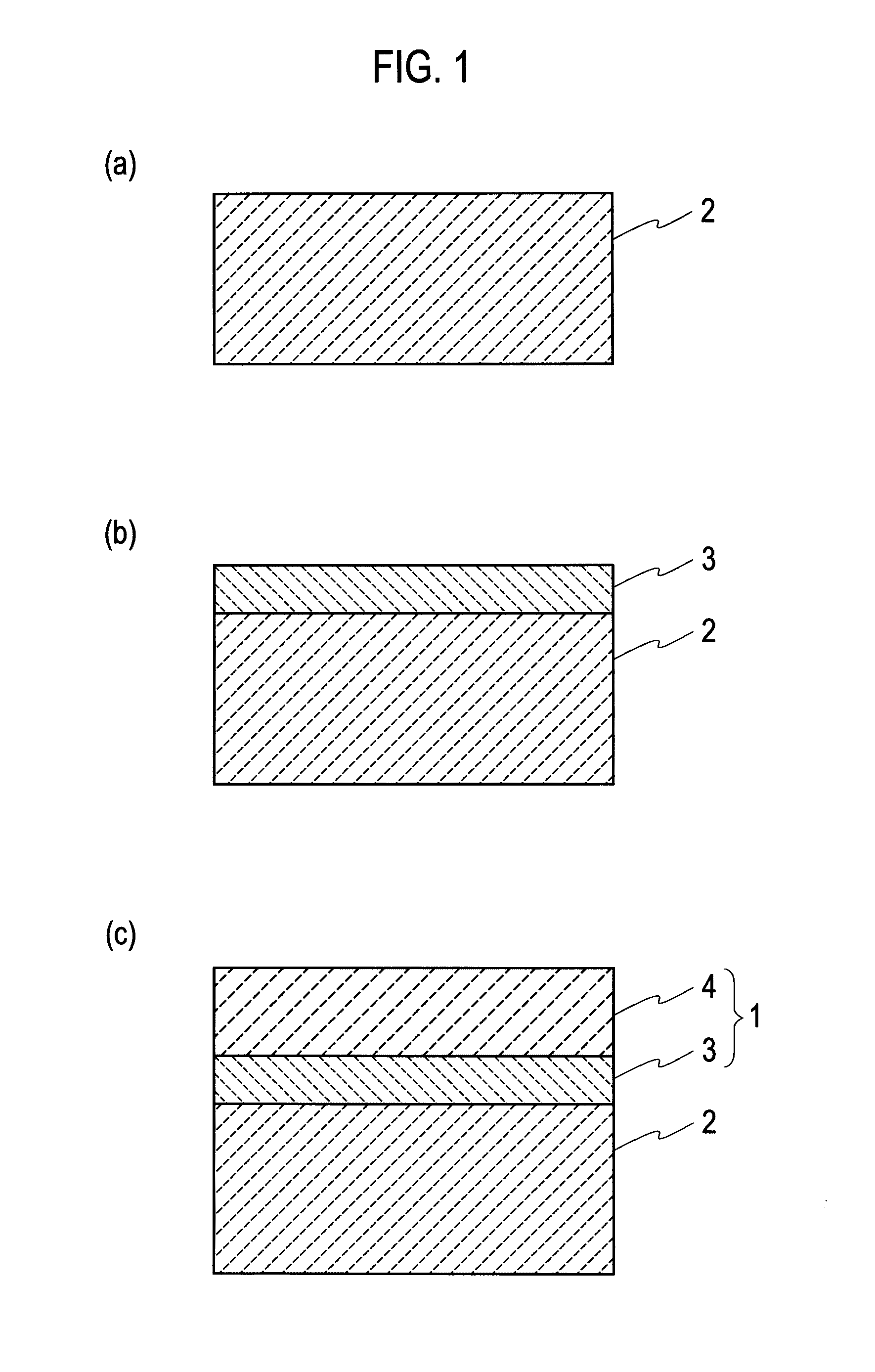
[0018]There will be described embodiments of the present invention with reference to FIG. 1 to FIG. 6.

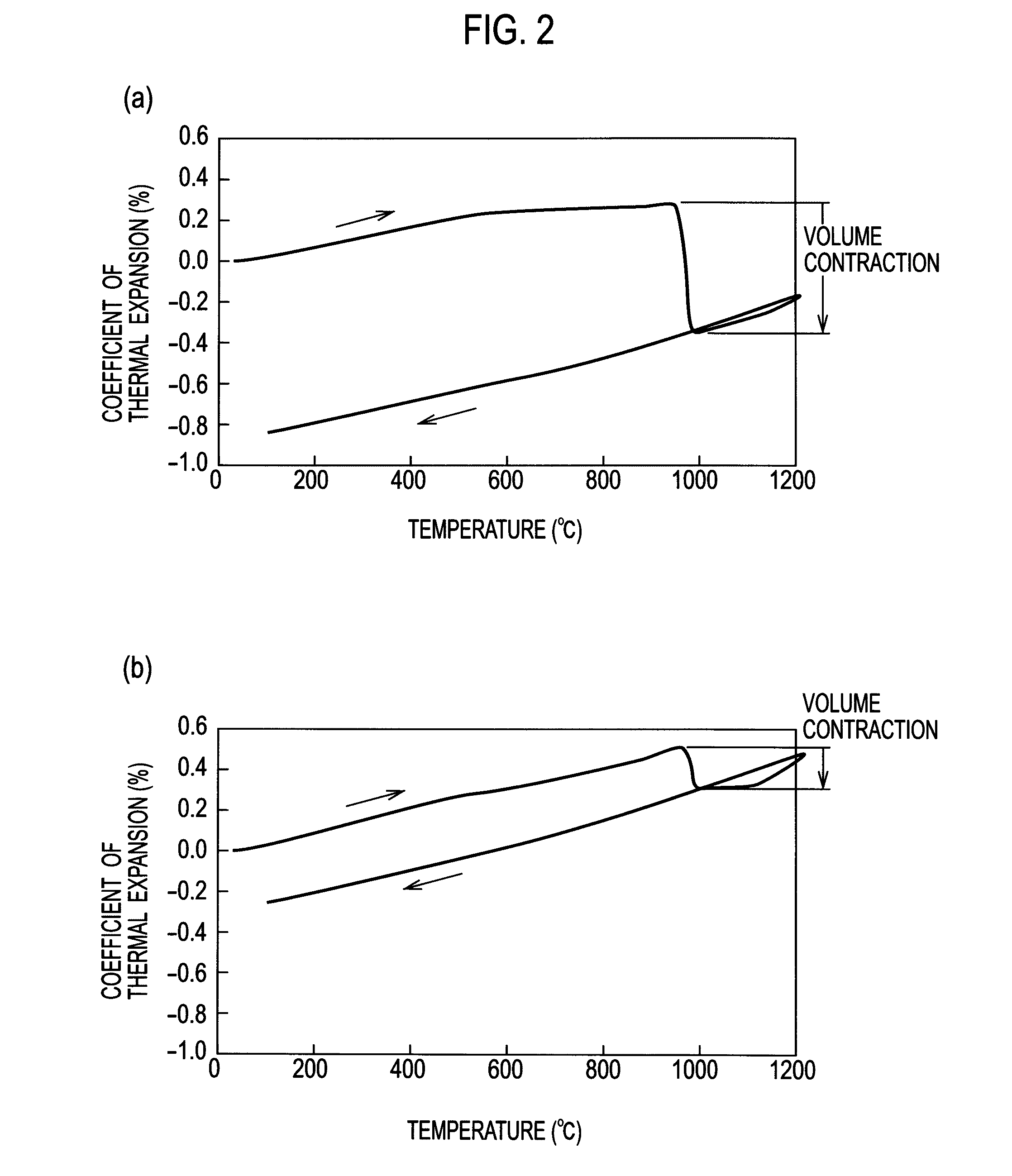
[0019][1] Description is now made of new knowledge constituting a premise of a coating structure and a surface processing method according to an embodiment of the present invention, with reference to FIG. 2.

[0020]FIG. 2 plots results of thermal expansion tests made on a test specimen A (as a comparative example: non-depicted) and a test specimen B (as an embodiment example: non-depicted) each simulating an intermediate layer.

[0021]More specifically, for the comparative example, there was a set of test specimens A modulating an intermediate layer, fabricated by a vacuum spray using a powder of 3Al2O3.2SiO2-mullite, as a spray material. For the embodiment example, there was a set of test specimens B modulating an intermediate layer, fabricated by a vacuum spray using, as a spray material, a combination of powder of 3Al2O3.2SiO2-mullite and powder of Yb2SiO5 being powders mixed (as a p...


PUM

PropertyMeasurementUnit
temperatureaaaaaaaaaa
heat resistanceaaaaaaaaaa
temperatureaaaaaaaaaa

Abstract

A high temperature component (2) has an intermediate layer (3) formed by a spraying on a surface in part thereof and comprised of an oxide ceramics set containing a glass, and an environment resistant coat (4) formed on a surface of the intermediate layer (3) and comprised of a coating material having a heat resistance and a water vapor wall-thinning resistance. The oxide ceramics set is a set of kinds of oxide ceramics adapted to be unchanged in crystalline phase, or isometric in cubic volume even when phase-changed, within a temperature range from a room temperature to 1,400 degrees C., the set of kinds of oxide ceramics having a coefficient of thermal expansion between a coefficient of thermal expansion of an SiC series ceramics matrix composite constituting the high temperature component (2) and a coefficient of thermal expansion of the coating material constituting the environment resistant coat (4).

Description

TECHNICAL FIELD [0001]The present invention relates to a coating structure and a surface processing method that afford to have a heat resistance and a water vapor wall-thinning resistance secured at least in part of a high temperature component such as a gas turbine component.BACKGROUND ART [0002]In recent years, there have been attentions focused on SiC series ceramics matrix composites (CMC) being small in specific gravity, and better in heat resistance than heat resistant alloys such as nickel alloys, as materials for high temperature components such as a gas turbine component to be used under high temperature gas environments containing water vapor. In this regard, it is known that in high temperature gases the water vapor acts on Si-containing materials, causing the wall to be thinned, so in use of such an SiC series ceramics matrix composite selected as a material for a high temperature component, the high temperature component should have a heat resistance and a water vapor w...

Claims


Application Information

Patent Timeline
Patent Type & Authority Applications(United States)
IPC IPC(8): C23C4/10B32B18/00B32B9/00
CPCC04B41/009C04B41/52C04B41/89C23C4/02C23C4/105C23C28/042F23M5/00F23M2900/05004F23R3/007F01D5/288C04B41/4527C04B41/5024C04B41/5037C04B41/5044C04B35/565C04B35/806C23C4/11
Inventor TANAKA, YASUTOMOMURATA, HIROSHIGE
Owner IHI CORP
Why Eureka
Try Eureka