Battery mounting and cooling system

a technology for which is applied in the field of battery mounting and cooling systems, can solve the problems of increasing the heat retention of batteries, reducing the life of batteries, and cumbersome and bulky assembling of batteries in plastic housings, so as to maximize the use of available space, save space, and less likely to be crushed

Inactive Publication Date: 2011-01-27
TESLA INC
View PDF17 Cites 10 Cited by
  • Summary
  • Abstract
  • Description
  • Claims
  • Application Information

AI Technical Summary

Benefits of technology

[0015]A system and method sandwiches batteries between a rigid substrate that can distribute force across multiple batteries or other structures such as walls placed among the batteries, making them less likely to be crushed when resisting a force applied to the substrate. The substrate can be shaped to approximately fit the cross section of the available space, maximizing the use of the available space. Multiple conductors connected to the batteries via holes in the substrate draw power as well as connect the batteries in parallel, series, or both, to provide the proper current and voltage. However, the holes in the substrate are designed to lessen the likelihood that the conductor connected to the positive terminal will be shorted to the negative body of the battery in the event a force is applied that brings the batteries closer to any of the conductors. Cooling may be accomplished via air cooling or water cooling. Air may be blown among the batteries via holes in the substrates and conductors, and optionally an insert with mounts for the batteries containing integrated air holes to save space. Alternatively, or in addition to the air cooling system, cooling tubes may be run among the batteries to allow heat to be drawn away from the batteries. The cooling tubes are run adjacent to the batteries, in a structure that contains a pair of adjacent cooling tubes. Each adjacent tube has an opposite direction of flow from the other tube, and a connector connects the tubes at one end, allowing the coolant to flow past the batteries in one direction, then loop back in the other direction, to allow the coolant to not only absorb heat from the batteries, but to also maintain a more constant temperature of the batteries than would be possible if coolant having a single direction of flow was run past the batteries. The tubes may be physically connected to each other to allow heat from the tubes to be exchanged, helping to maintain a more even temperature, of coolant through the tubes. The more constant temperature is maintained because the coolant along each section of the adjacent pair of tubes not only exchanges heat with the coolant in the adjacent tube, the coolest sections at the inlet are adjacent to the hottest sections at the outlet.

Problems solved by technology

However, as batteries become larger in size, the ratio of surface area to volume decreases, causing the battery to retain more heat, decreasing its life.
Assembling banks of batteries in a plastic housing can be cumbersome and bulky, so one manufacturer has built banks of conventional batteries in an alternative fashion by gluing batteries together in a side-by-side stack, like stacked firewood, and then connecting the terminals in each battery in the stack using a flexible nickel reed.
However, there are significant problems with this technique.
One such problem is that each of the stacks is not physically stable, because the form factor of each battery is not perfectly cylindrical.
Instead, each battery is slightly conical, and so the ends of each of the batteries in a stack can shift slightly, causing the joints between the batteries to fail.
This makes the glued stacks approach particularly unsuitable for environments in which significant vibration can occur, such as automotive applications.
The narrower ends of the batteries can be wrapped with tape to even out the diameter of each end of the batteries, but such wrapping is labor intensive, prone to error and subject to failure.
Another problem with stacks of glued batteries is mechanical strength.
If the end of a single battery is crushed, the chemicals in the battery can be compressed, causing a short circuit or other reaction that can heat the battery to an extent that a thermal runaway occurs, in which the heat from the initial reaction causes a thermal reaction to become self sustaining and propagate until the battery fails.
The heat from the battery can cause the adjacent batteries to incur the same thermal reaction until many or all of the batteries in the stack have failed.
Turning the batteries on their sides like stacks of firewood can make the problem worse in certain environments, such as when the stack has a large number of batteries in a vibration-prone environment.
The force from the vibrations can cause upper batteries to crush the lower batteries in the stack, causing the lower batteries to fail.
Additionally, conventional banks of batteries suffer from the problem that the conductors running across, and connected to, the positive “button” on top of the batteries can be pressed into the case of the battery during a significant impact, causing a short circuit between the positive button terminal and the electrically negative case.
This makes banks of batteries particularly unsuitable for applications such as an electric or hybrid automobile, or other applications in which the batteries are likely to be vibrated or crushed.
However, during an impact, the conductors that draw the positive current from the battery button terminal can burst through this insulating material to the metallic battery case, which is electrically connected to the negative terminal, thereby shorting the battery.
Still another problem with batteries that are arranged with their edges contacting is that the heat from the batteries can cause the batteries in the center of the stack to become hotter than the batteries at the edges.
When multiple banks of batteries are interconnected, the connections between each bank must be manually made, increasing the costs of manufacturing.
Wiring for voltage and temperature sensors at various points in the stack to allow for optimum performance further increase the costs of manufacturing.
Furthermore, the space in which the banks of batteries will be placed may not fit the banks exactly, requiring extra space to be allocated for the batteries, wasting space, and such space may be valuable in certain applications.
The banks can each be made relatively smaller to reduce any wasted space, but this approach increases the need for interconnection, adding additional cost and potential points of failure.

Method used


Image

  • Battery mounting and cooling system
  • Battery mounting and cooling system
  • Battery mounting and cooling system

Examples


Embodiment Construction

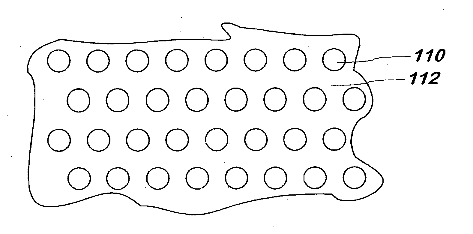
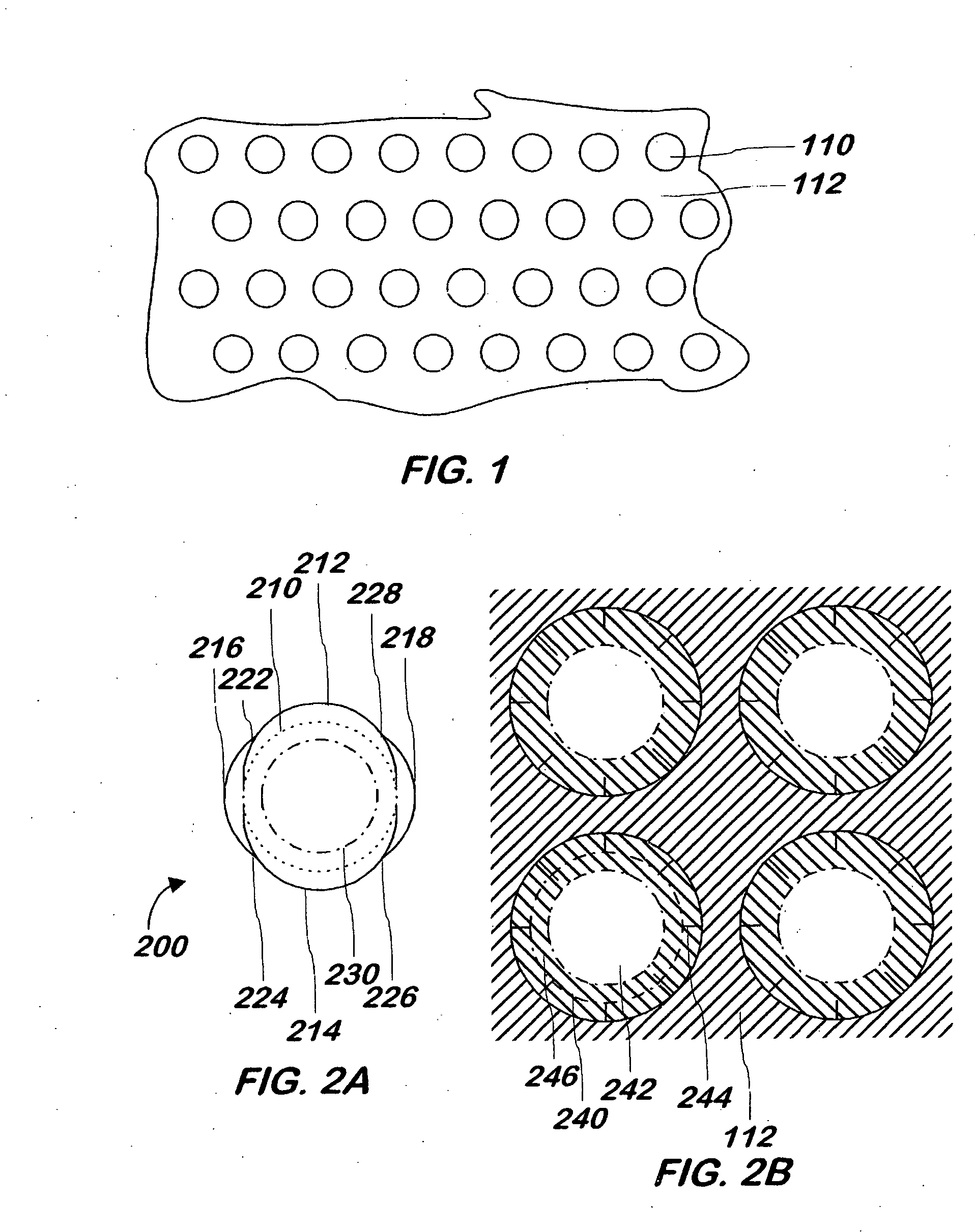
[0042]Referring now to FIG. 1, a substrate used to hold one or more sets of one or more batteries is shown according to one embodiment of the present invention. The batteries used in one embodiment are any conventional rechargeable batteries having an 18650 form factor, but other types of batteries and other form factors may be used.

[0043]The substrate 112 may be made of a material that electrically insulates one face of the substrate from the other face. The substrate 112 has at least two faces and may or may not be substantially flat. In one embodiment, the substrate 112 has two primary faces, both of which are made of an electrically insulating material. In one embodiment, the substrate is a single layer of such insulating material, such as fiberglass or plastic, and in another embodiment, one or more layers of a conducting material are formed in the substrate in the manner of a conventional printed circuit board to allow wiring for sensors to be run along as part of the substrat...


PUM

PropertyMeasurementUnit
electrically non-conductiveaaaaaaaaaa
thermally conductiveaaaaaaaaaa
anti-freezeaaaaaaaaaa

Abstract

A battery system is provided in which the batteries are mounted between a pair of substrates, the system further including at least one cooling tube mounted next to the batteries, the cooling tube used to withdraw heat from the batteries via a circulating liquid coolant.

Description

CROSS-REFERENCE TO RELATED APPLICATIONS [0001]This application is a continuation of U.S. patent application Ser. No. 11 / 129,118, filed May 12, 2005, the disclosure of which is incorporated herein by reference for any and all purposes.FIELD OF THE INVENTION [0002]The present invention is related to battery systems and more specifically to systems containing multiple batteries.BACKGROUND OF THE INVENTION[0003]Portable electric devices can make use of batteries as a source of power. For example, conventional lithium-ion batteries may be used to power portable or mobile devices.[0004]Conventional batteries generate significant heat from their cores. Exposing a battery to heat can significantly shorten its life, and thus, it is desirable to dissipate the heat from a battery.[0005]To obtain higher current, voltage, or both, from a battery, the battery can be made larger. However, as batteries become larger in size, the ratio of surface area to volume decreases, causing the battery to reta...

Claims


Application Information

Patent Timeline
Patent Type & Authority Applications(United States)
IPC IPC(8): H01M10/50H01M50/204H01M50/509H01M50/512H01M50/529
CPCH01M2/105H01M2/10H01M2/24H01M6/42H01M10/5004H01M10/5008H01M10/5016H01M10/503H01M10/5053H01M10/5057H01M10/5067H01M10/5071H01M10/5075H01M10/5095H01M2/204H01M10/6563H01M10/6556H01M10/6554H01M10/613H01M10/625H01M10/643H01M10/663H01M10/6567H01M10/617H01M10/6565Y10T29/49108Y02E60/10H01M50/213H01M50/529H01M50/204H01M50/509H01M50/512H01M10/653H01M10/6557H01M10/6568
Inventor STRAUBEL, JEFFREY B.BERDICHEVSKY, EUGENELYONS, DAVIDCOLSON, THOMASEBERHARD, MARTINWRIGHT, IANFERBER, ROBERT
Owner TESLA INC
Why Eureka
Try Eureka