Electric power steering device and method for controlling the same

a technology of electric power steering and electric motor, which is applied in the direction of steering initiation, instruments, vessel construction, etc., can solve the problems of excessive light steering or lowering rigid feel, and the prior art cannot solve the above presented problems, and achieve the effect of simple structure and effective application of assist for

Active Publication Date: 2011-01-27
JTEKT CORP
View PDF4 Cites 24 Cited by
  • Summary
  • Abstract
  • Description
  • Claims
  • Application Information

AI Technical Summary

Benefits of technology

[0007]Accordingly, it is an objective of the present invention to provide an electric power steering device and a method for controlling the same that are capable of, with a simple structure, effectively applying assist force even during an extended period of traveling forward in a straight line.
[0009]That is, when a vehicle is traveling on a canted road, a steering torque required for maintaining the steering is a small value that is within the dead zone, for example. Even in this case, if the steering is maintained for a long time, the integrated value of the steering torque increases as the period of steering maintaining is extended. Therefore, by using the integrated value of the steering value (or an equivalent value), it is possible to determine whether the assist force needs to be increased and to accurately perform the computation of the compensation component used for increasing the assist force. The compensation component for increasing the assist force helps maintaining the steering for an extended period, thereby reducing the burden on the driver while the vehicle is traveling forward in a straight line. In contrast, when the vehicle is traveling forward in a non-straight line, the compensation component can cause excessively light steering or lowered rigid feel, due to excessive assist. However, in accordance with the above configuration, the compensation component is superimposed on the basic component of assist force only when the vehicle is traveling forward in a straight line. Thus, the excessively light steering or lowered rigid feel due to excessive assist are prevented. As a result, it is possible to effectively apply an assist force when the vehicle travels forward in a straight line for an extended period of time using a simple structure, while maintaining a favorable steering feel when the vehicle travels forward in a non-straight line.
[0012]When the vehicle is traveling forward in a straight line, the assist force tends to be insufficient if the steering needs to be maintained for an extended time, for example, when the vehicle is traveling on a canted road. On the other hand, if the compensation component is increased based on the integrated value of steering torque when the vehicle travels forward in a straight line for a short period of time, excessive assist can cause undesirable effects. However, by computing the integration of the steering torque only when the vehicle is traveling forward in a straight line as in the configuration, the compensation component is not excessively increased. Excessive assist and accompanying disadvantages are therefore prevented. As a result, it is possible to effectively apply assist force when the vehicle travels forward in a straight line for an extended period of time, while achieving a favorable steering feel when the vehicle travels forward in a non-straight line.
[0014]Accordingly, even if the detected steering torque is minute, the influence of displacement of neutral point or detection errors of the steering torque is eliminated, so that the compensation component is highly accurately computed.

Problems solved by technology

In contrast, when the vehicle is traveling forward in a non-straight line, the compensation component can cause excessively light steering or lowered rigid feel, due to excessive assist.
The prior art therefore cannot solve the above presented problems.

Method used


Image

  • Electric power steering device and method for controlling the same
  • Electric power steering device and method for controlling the same
  • Electric power steering device and method for controlling the same

Examples


Embodiment Construction

[0030]An electric power steering device (EPS) 1 according to one embodiment of the present invention will now be described with reference to the drawings.

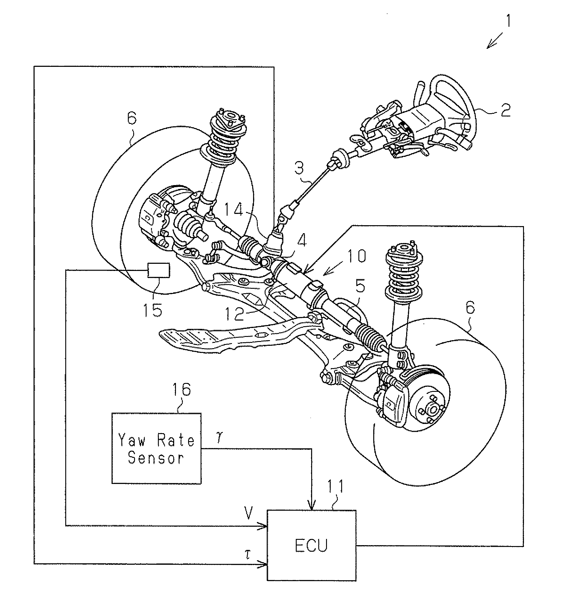
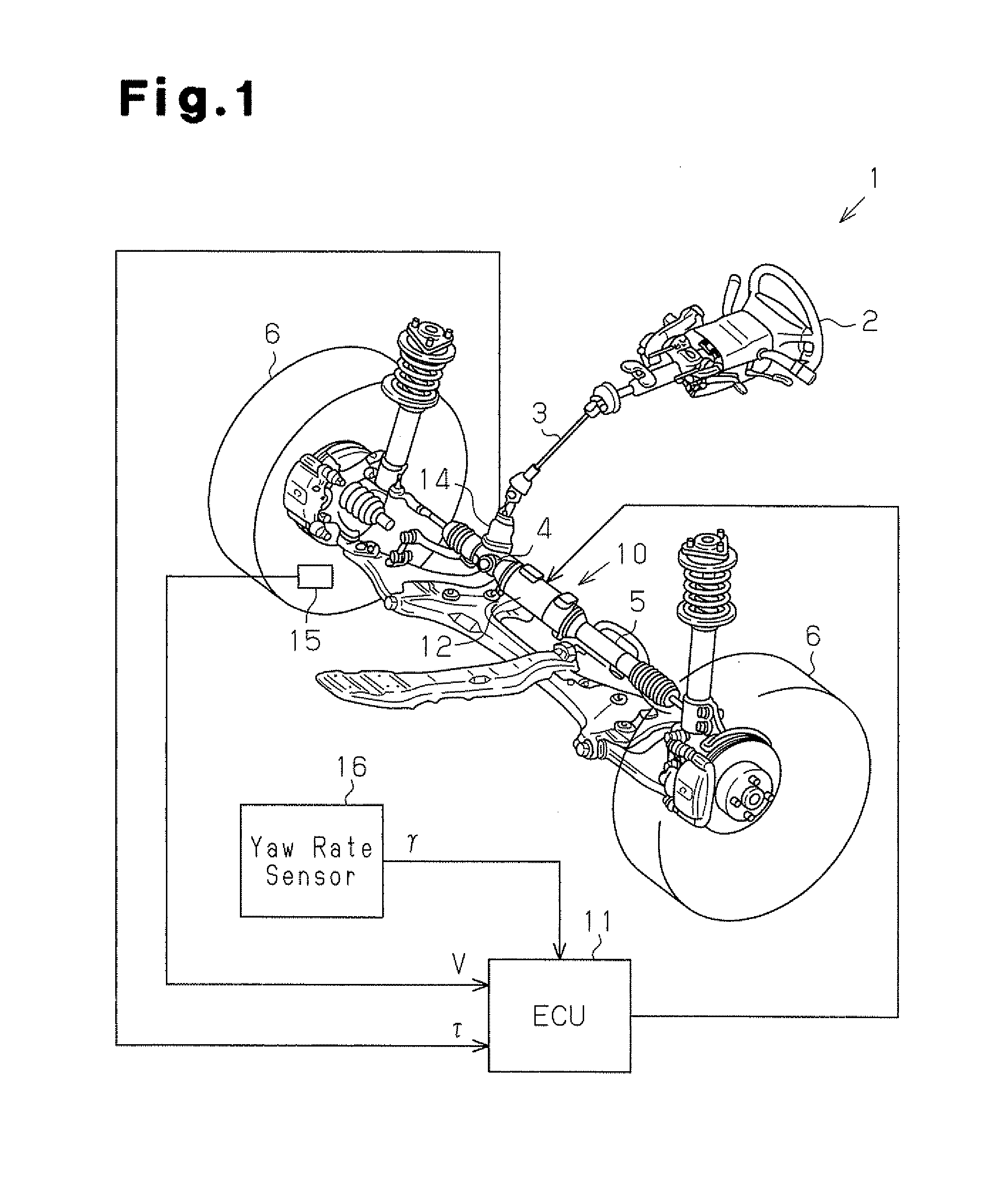
[0031]As shown in FIG. 1, a steering wheel 2 is fixed to a steering shaft 3. The steering shaft 3 is coupled to a rack 5 via a rack-and-pinion mechanism 4. Rotation of the steering shaft 3 accompanying a steering operation is converted into a reciprocating linear motion of the rack 5 by the rack-and-pinion mechanism 4. The reciprocating linear motion of the rack 5 changes the steered angle of steerable wheels 6, or the tire angle, thereby changing the travel direction of the vehicle.

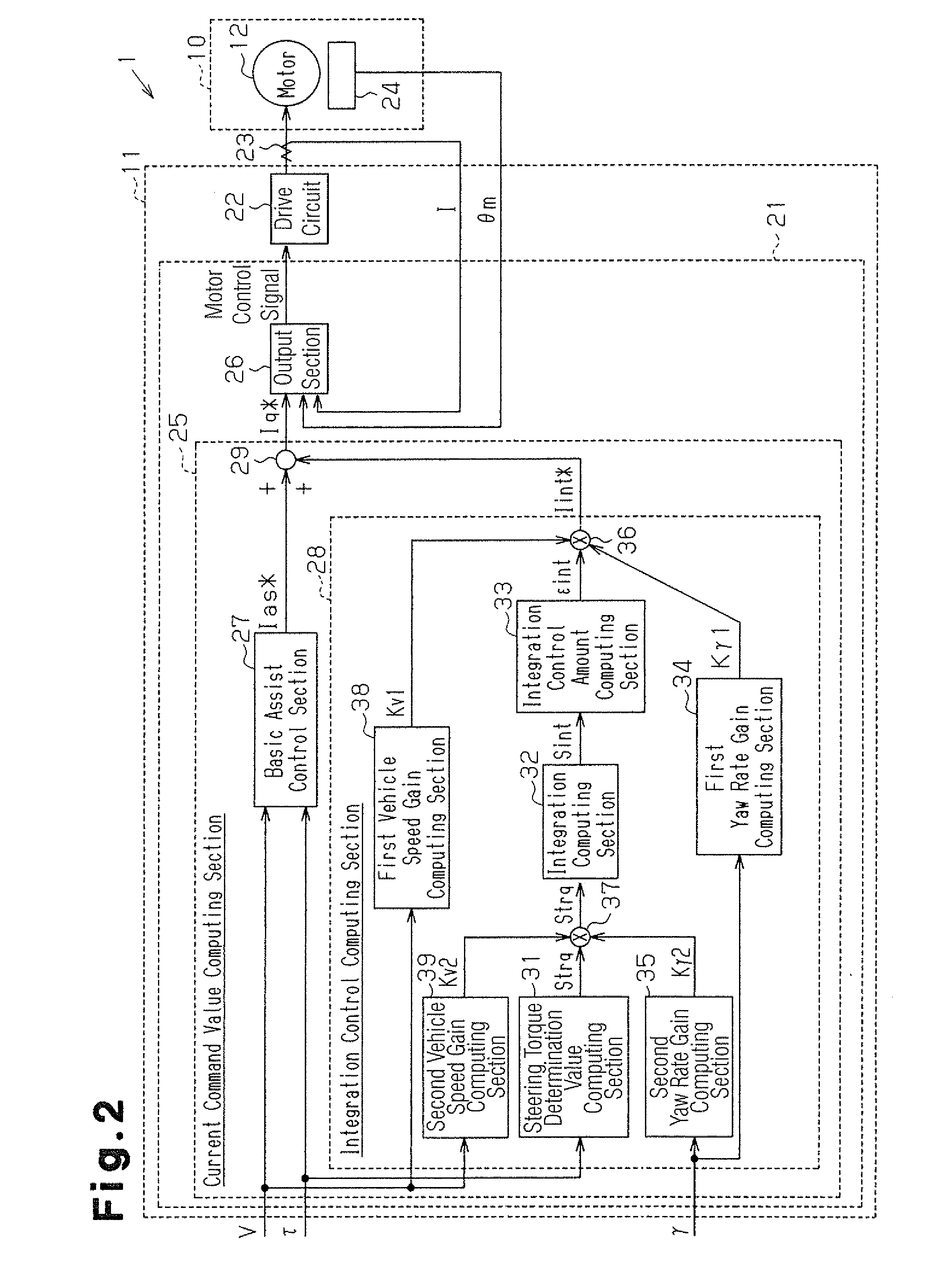
[0032]The EPS 1 includes an EPS actuator 10 serving as a steering force assist device, and an ECU 11 serving as control device. The EPS actuator 10 applies an assist force that assists a steering operation of the steering system. The ECU 11 controls operation of the EPS actuator 10.

[0033]The EPS actuator 10 is a rack type EPS actuator in which a motor 1...


PUM


Abstract

A current command value computing section includes an integration control computing section. Based on an integration of the steering torque τ, the integration control computing section computes a steering torque integration control amount Iint*, which is a compensation component for increasing the assist force. The integration control computing section functions as a determining device that determines whether the vehicle is traveling forward in a straight line. When the determining device determines that the vehicle is traveling forward in a straight line, the integration control computing section outputs the steering torque integration control amount Iint* to an adder. The current command value computing section superimposes the steering torque integration control amount Iint* on a basic assist control amount Ias* computed by a basic assist control section, and outputs the obtained value, as a current command value Iq* corresponding to a target assist force, to an output section.

Description

TECHNICAL FIELD[0001]The present invention relates to an electric power steering device and a method for controlling the apparatus.BACKGROUND ART[0002]Conventional power steering device for a vehicle include an electric power steering device (EPS) provided with a motor as a drive source. Generally, an EPS computes a basic component assist force applied to the steering system, or a basic assist control amount, based on a detected steering torque. In the computation of the basic assist control amount, a dead zone is established in which, when the steering torque is in a predetermined range, the basic assist control amount is set to zero regardless of the value of the steering torque. Thus, in a range including the neutral steering position, excessive assist force is not applied, and the rigid feel of steering is increased.[0003]The surfaces of roads for vehicles are often inclined along the transverse direction in order to improve drainage performance. When a vehicle is traveling forw...

Claims


Application Information

Patent Timeline
Patent Type & Authority Applications(United States)
IPC IPC(8): B62D6/08
CPCB62D6/04B62D5/0463
Inventor TAMAIZUMI, TERUTAKAEKI, HIROZUMIAONO, SHINYAHASEGAWA, JUNKITA, MASAYUKI
Owner JTEKT CORP
Why Eureka
Try Eureka