Acceleration control device

a technology of acceleration control and acceleration, which is applied in the direction of electric controllers, adaptive control, instruments, etc., can solve the problems of giving uncomfortable driving to passengers and drivers of vehicles, and lack of necessary acceleration

Inactive Publication Date: 2011-01-27
DENSO CORP +1
View PDF15 Cites 30 Cited by
  • Summary
  • Abstract
  • Description
  • Claims
  • Application Information

AI Technical Summary

Benefits of technology

[0077]According to the acceleration control device according to the present invention, it is possible to calculate the acceleration in the longitudinal direction as the gradient acceleration even if the driver's vehicle is running on the road with an inclination along the longitudinal direction of the driver's vehicle.

Problems solved by technology

This would cause various problems, for example:
(a-4) giving uncomfortable driving to the passengers and driver of the vehicle because a small drive torque is generated in the driver's vehicle.
This causes lack of a necessary acceleration.

Method used


Image

  • Acceleration control device
  • Acceleration control device
  • Acceleration control device

Examples


first embodiment

[0098]A description will be given of the cruise assist system 1 equipped with a cruise assist ECU 20 (as acceleration control device) according to a first embodiment of the present invention.

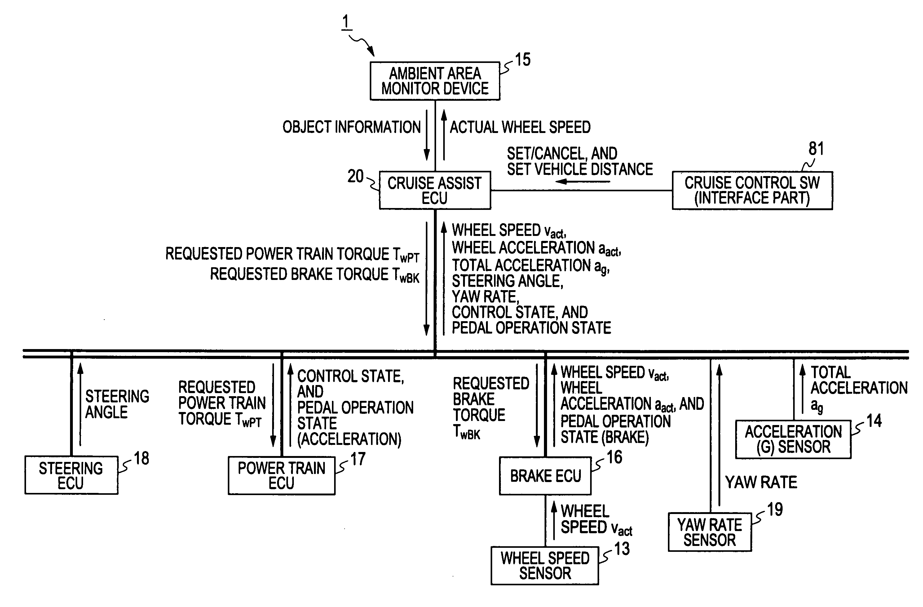
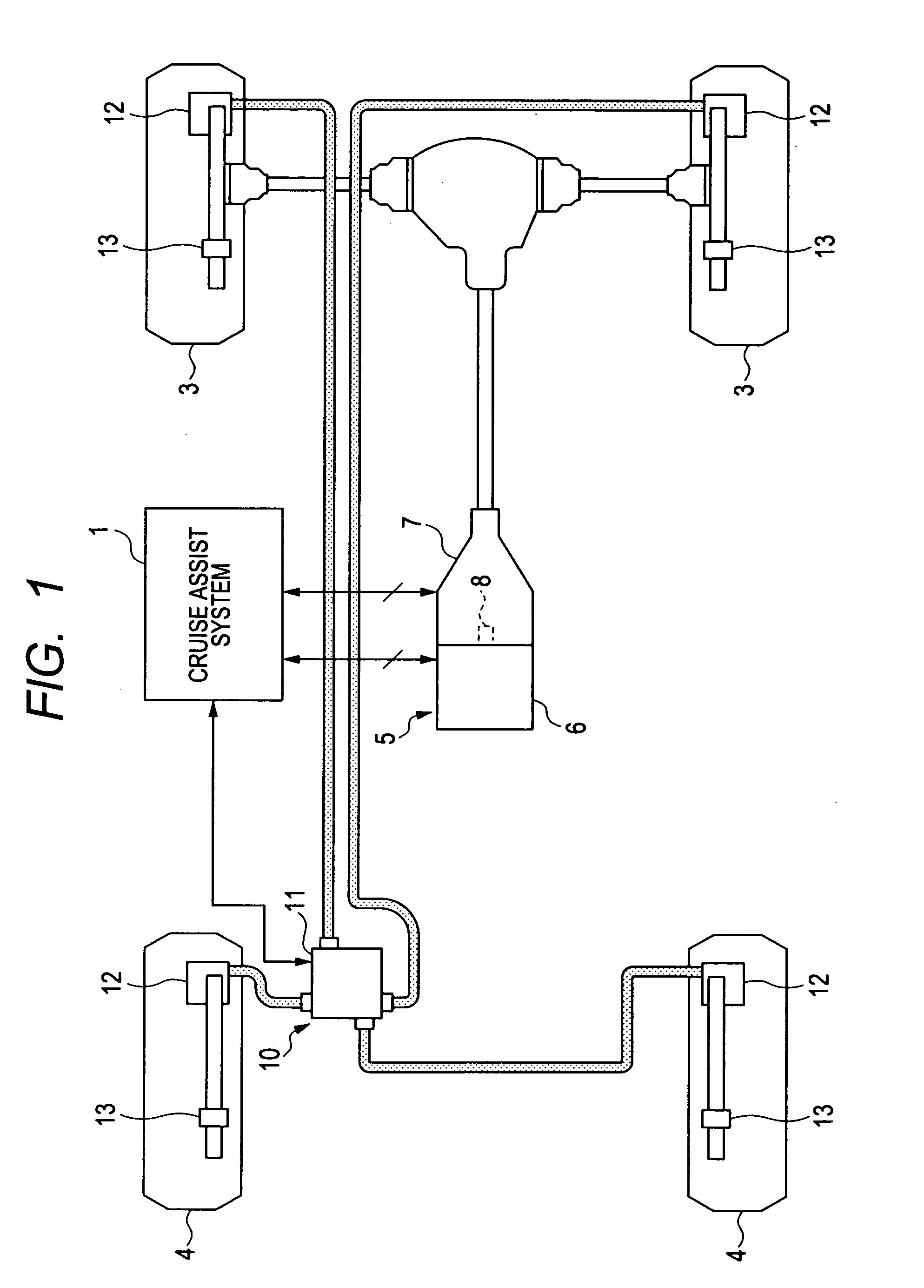
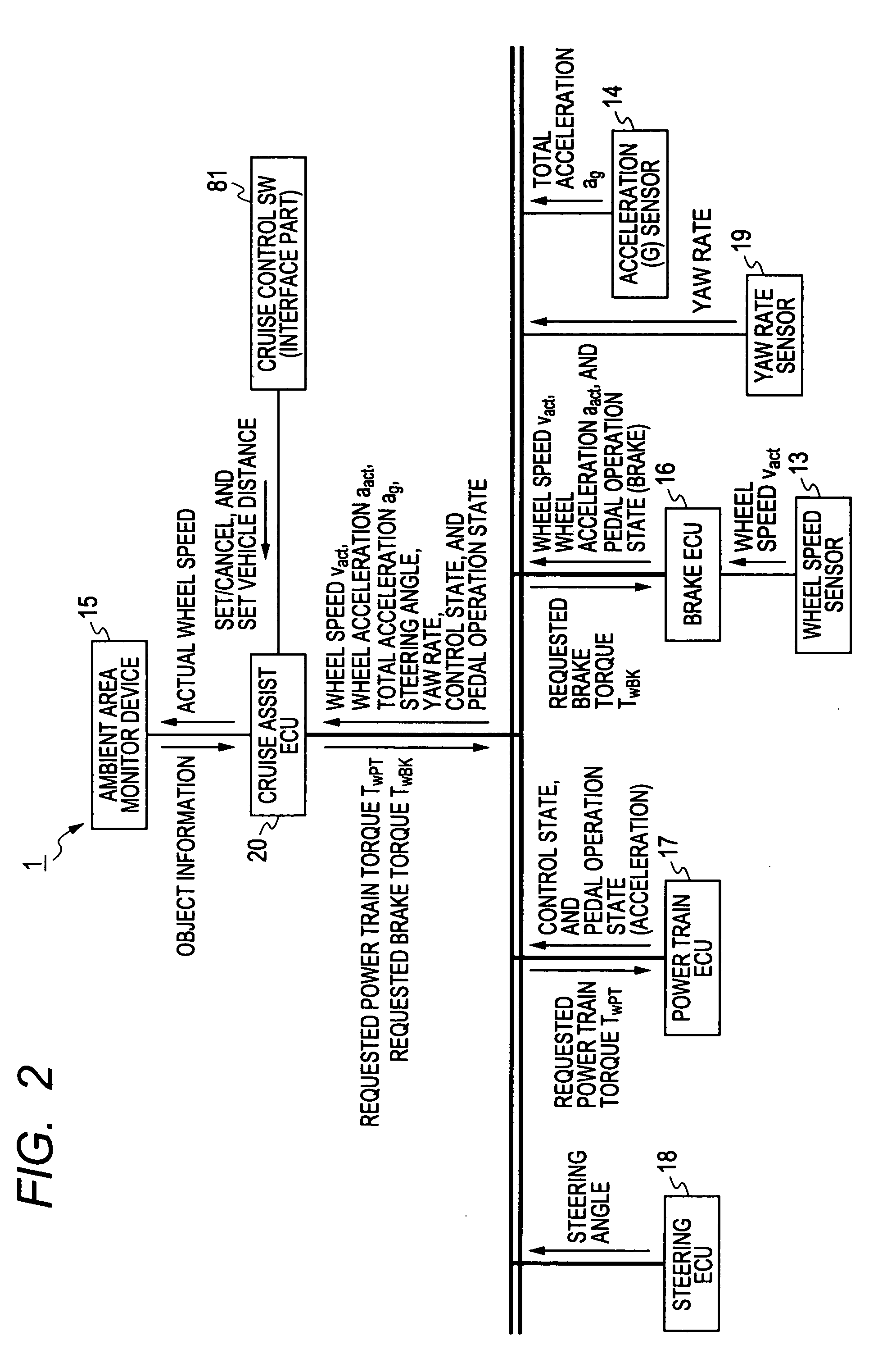
[0099]FIG. 1 is a view schematically showing a vehicle (driver's vehicle) equipped with the cruise assist system 1 according to the present invention. The cruise assist system 1 has the cruise assist ECU 20 according to the first embodiment of the present invention. FIG. 2 is a block diagram showing a schematic configuration of the cruise assist system 1 having the cruise assist ECU 20 shown in FIG. 1.

[0100]Hereinafter, a vehicle equipped with the cruise assist system 1 having the cruise assist ECU 20 will be referred to as the “driver's vehicle”.

[0101]As shown in FIG. 1, the driver's vehicle has at least a power train mechanism 5, a brake mechanism 10, and a cruise assist system 1. The cruise assist system 1 controls the power train mechanism 5 and the brake mechanism 10 in order to assist the ...

second embodiment

[0238]A description will be given of the cruise assist system equipped with cruise assist ECU 20 according to a second embodiment of the present invention.

[0239]The cruise assist system has an acceleration control device which is different in configuration and operation from the acceleration control device according to the first embodiment, previously described. Other components of the cruise assist ECU 20 according to the second embodiment are the same as those of the first embodiment. The same components are referred to with the same reference numbers and the explanation thereof is omitted here for brevity.

20>

[0240]FIG. 10 is a block diagram showing a schematic configuration of the cruise assist system equipped with the cruise assist ECU 20 according to the second embodiment of the present invention.

[0241]The cruise assist ECU 20 according to the second embodiment serves as a target acceleration calculator 21 to repeatedly calculate the target acceleration areq and the request jer...


PUM


Abstract

In a cruise assist ECU, when a vehicle drive state is changed from a running state to a state immediately before vehicle stop or from a stop state to a state immediately after vehicle start, a feedback torque gain compensation part changes a feedback torque gain to a second set value, and maintain it during the state immediately before vehicle stop or the state immediately after vehicle start. Because the second set value is smaller than a first set value, a response delay is increased in feedback control of the feedback torque control part when the first set value of the feedback torque gain is switched to the second set value. This makes it possible to slowly change the FB control value during the transition state in elapse of time, and prevent a brake or damping torque generated in the vehicle from being excessively changed in FB control.

Description

CROSS-REFERENCE TO RELATED APPLICATION[0001]This application is related to and claims priority from Japanese Patent Application No. 2009-170341 filed on Jul. 21, 2009, the contents of which are hereby incorporated by reference.BACKGROUND OF THE INVENTION[0002]1. Field of the invention[0003]The present invention relates to an acceleration control device capable of controlling the drive speed of a vehicle in order to obtain a target acceleration which is required by the driving state of the vehicle.[0004]2. Description of the Related Art[0005]An adaptive cruise control system (or an adaptive cruise assist system has been known and is mounted to vehicles. Such a type of the adaptive cruise control system is equipped with a forward scene observation device, a target acceleration calculation device, and an acceleration control device. The forward scene observation device detects the presence of a front vehicle which is running or stopped in front of the driver's vehicle. The target accel...

Claims


Application Information

Patent Timeline
Patent Type & Authority Applications(United States)
IPC IPC(8): G06F19/00B60K31/00B60T7/12B60W10/04B60W10/06B60W10/18B60W10/188B60W10/20B60W30/00B60W30/14B60W40/02F02D29/02G05B11/32G05B13/02G08G1/16
CPCB60W30/16B60W40/105B60W50/06B60W2550/142B60W2520/14B60W2520/28B60W2720/106B60W2050/0042B60W2552/15B60W2540/18
Inventor UMAKOSHI, MOTOAKIKUMABE, HAJIMETAKEDA, MASAYOSHIHANZAWA, MASATOSHI
Owner DENSO CORP
Why Eureka
Try Eureka