
Multiple interface support

a multi-interface and support technology, applied in the field of modular automation, can solve the problems of limited interoperability and consistency between such products, the complexity of the system, and the challenge of communication and functional cooperation between the components of the industrial automation system

Active Publication Date: 2011-01-27
ROCKWELL AUTOMATION TECH
View PDF98 Cites 17 Cited by
  • Summary
  • Abstract
  • Description
  • Claims
  • Application Information

AI Technical Summary

Benefits of technology

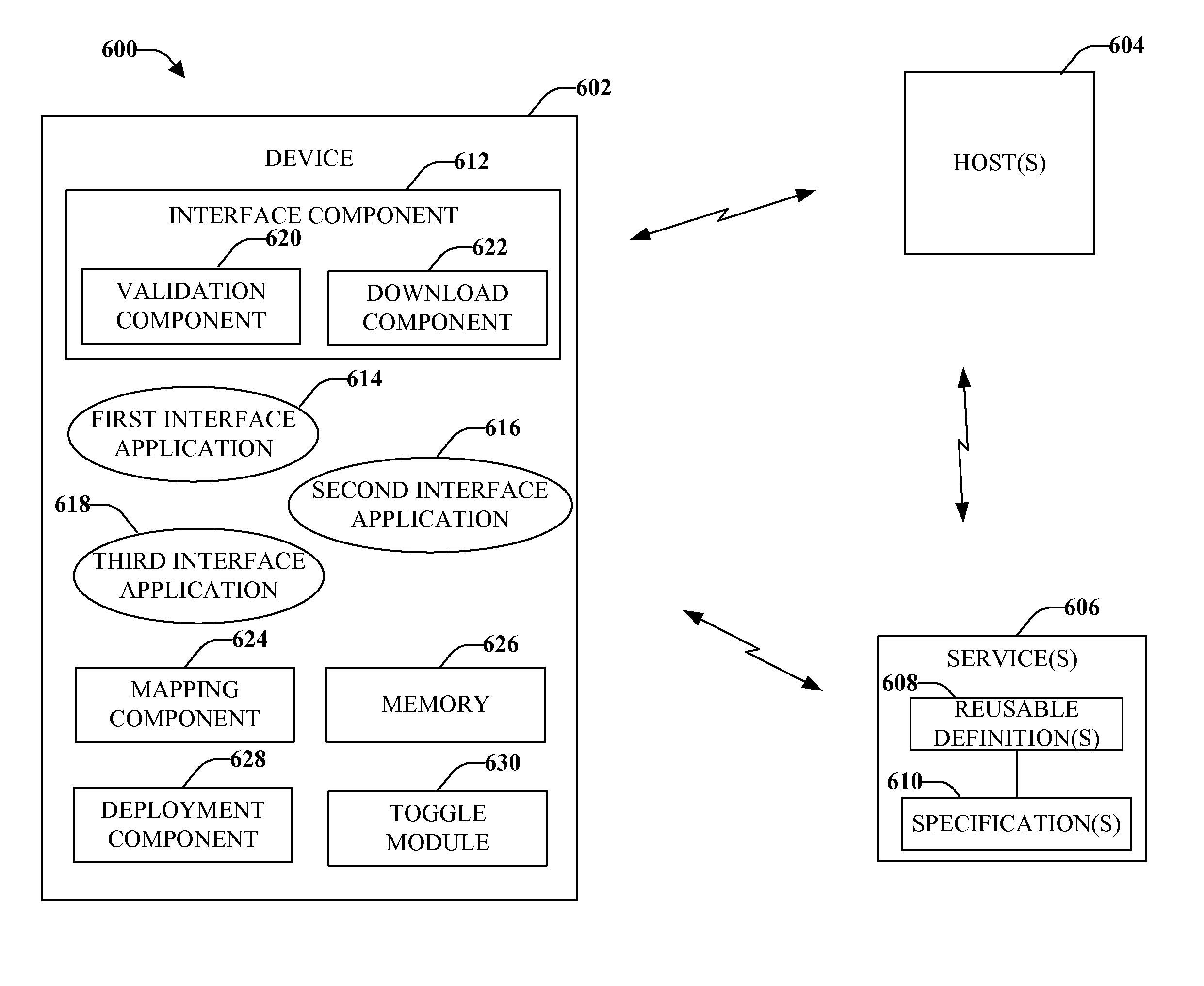
An aspect relates to a device comprising an interface component that obtains a set of alternative interface applications for an industrial automation system. The device also comprises a deployment component that enables a first interface application from the set of alternative interface applications. The interface component can maintain support for each interface application included in the set of alternative interface applications, wherein each interface application is a different interface version.

Problems solved by technology

As systems have become more complex, however, communications and functional cooperation between components of the industrial automation system has become a challenge.
For instance, when users purchase multiple products from one or more vendors, there is often limited interoperability and consistency between such products.
Limited product and component consistency suggest that techniques engineers learn for one product do not necessarily carry over to other implementations.
Often, integration of products in the industrial automation system is complex and difficult to manage.
Process and control engineers cannot easily code and configure their respective components without concern for other system components, which may have different manufacturers and different platforms.
Another problem with integration of products is that process and control engineers focus on underlying technical details, including implementation and glue logic, rather than the application level concerns, for example process information.
In another case, system design does not sufficiently enable trade-offs between overhead burden (memory footprint, CPU (central processing unit) cycles, and so forth) and application coupling.
Current solutions however do not facilitate a smooth and uncomplicated transition for the respective changes.
Multiple technologies underneath many vendors' products complicate configuration and management of systems.
Such complexity hinders the system's capacity to provide higher-level information and can reduce the ability to configure such systems.

Method used


Image

  • Multiple interface support
  • Multiple interface support
  • Multiple interface support

Examples


Embodiment Construction

Various aspects are now described with reference to the drawings. In the following description, for purposes of explanation, numerous specific details are set forth in order to provide a thorough understanding of one or more aspects. It may be evident, however, that such aspect(s) may be practiced without these specific details. In other instances, well-known structures and devices are shown in block diagram form in order to facilitate describing these aspects.

As used in this application, the terms “component,”“module,”“object”, “service,”“system,”“interface,” or the like are generally intended to refer to a computer-related entity, either hardware, a combination of hardware and software, software, or software in execution. For example, a component can be, but is not limited to being, a process running on a processor, a processor, a hard disk drive, multiple storage drive (of optical and / or magnetic storage medium), an object, an executable, a thread of execution, a program, and / or ...


PUM


Abstract

Aspects describe multiple interface support that provides dynamic switching between new and old interface revisions. A first interface application is selected from a set of alternative interface applications for an industrial automation system. Support for each interface application included in the set of alternative interface applications is provided. A second interface application is downloaded and associated with the first interface application. The second interface application is enabled during runtime. If needed, the second interface application can be selectively disabled and an operation resumed with the first interface application.

Description

TECHNICAL FIELDThe subject disclosure relates generally to industrial control systems and more particularly to modular automation within industrial control systems.BACKGROUNDIndustrial control systems can employ complex mechanical, electronic, electro-mechanical, and / or robotic machinery to perform various automated mechanical and / or electrical functions. Examples of machinery include industrial motors, pumps, conveyors, escalators, drills, refrigeration systems, and so forth. An industrial control system can utilize one or more control devices to activate or deactivate the machinery and / or to determine an appropriate level of activation for the machinery (e.g., an amount of current to supply to a variable input motor). Additionally, the control devices can be associated with logical program code that determines an appropriate time, degree, manner, and other criteria for operation of the machinery. For example, the determination can be based on various circumstances, including an ou...

Claims


Application Information

Patent Timeline
IPC IPC(8): G06F9/00
CPCG05B19/0426G05B19/056G05B19/41845G06F9/541G05B2219/23389G05B2219/23467G05B2219/31124G05B2219/13063Y02P90/02
Inventor PLACHE, KENNETHSEGER, III, DANIEL B.STARON, RAYMONDKRETSCHMANN, ROBERT J.JASPER, TARYLJARRETT, JAMES HARRYBRANDES, RUSSELLBLISS, RONALDKALAN, MICHAELGOVINDARAJ, SUBBIANHALL, KENWOODREICHARD, DOUGLAS J.
Owner ROCKWELL AUTOMATION TECH
Learn More