Thermal flow meter

a flow meter and flow rate technology, applied in the direction of volume/mass flow measurement, measurement devices, instruments, etc., can solve the problems of insufficient adjustment accuracy, inability to obtain sufficient adjustment accuracy, and inability to meet the requirements of mass production process mechanical trimming devices, etc., to achieve high accuracy, low cost, and high accuracy. simplicity

Active Publication Date: 2011-02-03
HITACHI ASTEMO LTD
View PDF4 Cites 23 Cited by
  • Summary
  • Abstract
  • Description
  • Claims
  • Application Information

AI Technical Summary

Benefits of technology

[0019]According to the above-mentioned features, it is possible to realize a circuit configuration equivalent to the configuration that adjusts a resistance value by using a variable resistance. In addition, the circuit configuration with high accuracy can be achieved because no variable resistance having a large fluctuation in addition to a high resistance temperature coefficient is required. In addition, the above-mentioned voltage generation circuit can arbitrarily set a terminal voltage of the second series circuit. Accordingly, advantageous effects of expanding the adjustment range and of improving the adjustment resolution are obtained.
[0020]According to the present invention, provided is a thermal flow rate sensor with high accuracy and low cost that adjusts a resistance balance with high accuracy and simplicity without using mechanical resistance trimming.

Problems solved by technology

Accordingly, there is a limitation in adjustment accuracy for a heating temperature of a heat-generating resistor.
Furthermore, there is a problem in that sufficient adjustment accuracy cannot be obtained when the resistance value of the variable resistance is adjusted by using mechanical trimming.
In addition, there is also a cost problem in that mechanical trimming devices are required in a mass production process and trimming requires much time.

Method used


Image

  • Thermal flow meter
  • Thermal flow meter
  • Thermal flow meter

Examples


first embodiment

[0033]A first embodiment according to the present invention will be described below.

[0034]A drive circuit and a detection circuit in a thermal flow meter according to the embodiment will be described.

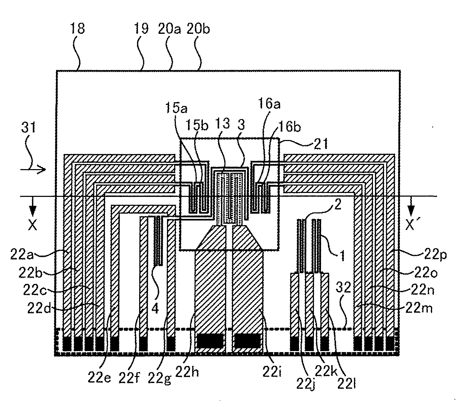
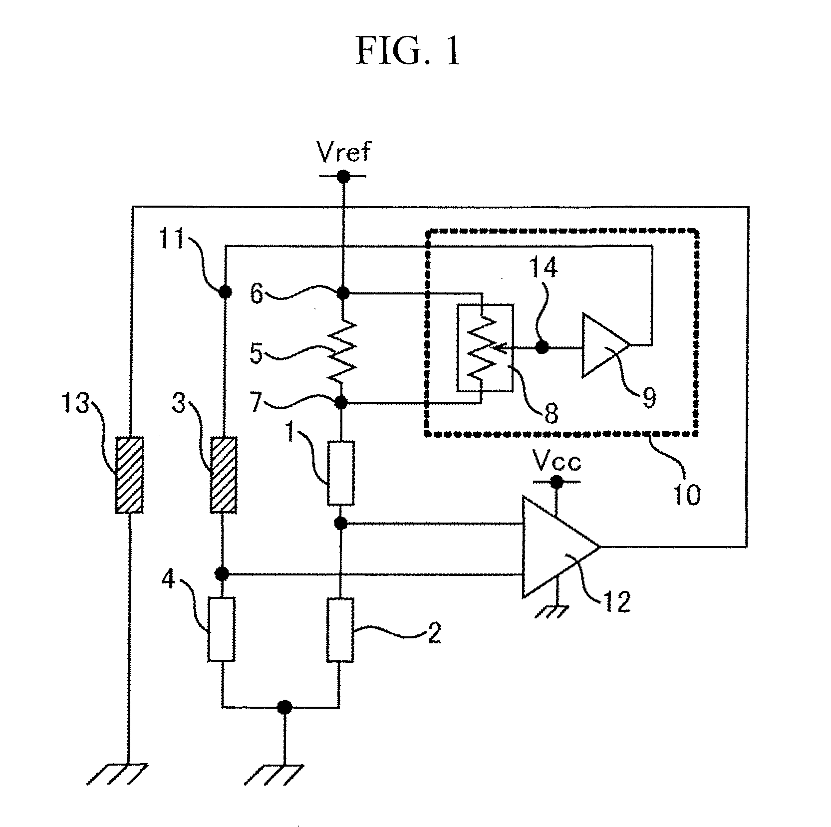
[0035]FIG. 1 shows a drive circuit of a heat-generating resistor 13. The drive circuit includes a temperature measuring resistor 3 (third resistor) that is placed near the heat-generating resistor 13 and whose resistance value varies with the temperature in the heat-generating resistor 13, temperature measuring resistors 1 (first resistor), 2 (second resistor), and 4 (fourth resistor) whose resistance values vary with the temperature in a fluid to be measured, and a fixed resistance 5 whose resistance value hardly depends on the temperature. The resistance balance of these resistors controls the heating temperature in the heat-generating resistor 13. A temperature measuring resistor, which is generally called as a temperature-sensitive resistor as well, has a resistance temperature coef...

second embodiment

[0059]A second embodiment according to the present invention will be described below.

[0060]A drive circuit in a thermal flow meter according to the embodiment will be described. In the embodiment, the portions different from the first embodiment will be described.

[0061]FIG. 7 shows a drive circuit of a heat-generating resistor 13. The drive circuit includes: a temperature measuring resistor 3 (third resistor) that is placed near the heat-generating resistor 13 and whose resistance value varies with the temperature in the heat-generating resistor 13; fixed resistances 5, 45 (fourth resistor), and 46 (second resistor) whose resistance values hardly depend on the temperature; and a temperature measuring resistor 1 (first resistor) whose resistance value varies with the temperature in a fluid to be measured. The resistance balance of these resistors controls the heating temperature in the heat-generating resistor 13.

[0062]A reference voltage Vref that is a first reference potential is a...

third embodiment

[0069]A third embodiment according to the present invention will be described below.

[0070]A drive circuit in a thermal flow meter according to the embodiment will be described. In the embodiment, the portions different from the first embodiment will be described.

[0071]FIG. 8 shows a drive circuit of a heat-generating resistor 13. The drive circuit includes: a temperature measuring resistor 3 (second resistor) that is placed near the heat-generating resistor 13 and whose resistance value varies with the temperature in the heat-generating resistor 13; temperature measuring resistors 1 (first resistor), 2 (third resistor), and 4 (fourth resistor) whose resistance values vary with the temperature in a fluid to be measured; and the fixed resistance 5 whose resistance value hardly depends on the temperature. The resistance balance of these resistors controls the heating temperature in the heat-generating resistor 13.

[0072]A reference voltage Vref that is a first reference potential is app...


PUM


Abstract

Provided is a heating temperature adjustment circuit in a thermal flow meter capable of adjusting fluctuations of a heating temperature of a heat-generating resistor due to fluctuations of resistances with high accuracy and low cost. The thermal flow meter comprises: a heat-generating resistor that generates heat when a current flows therethrough; a first temperature measuring resistor, a second resistor, a third resistor, and a fourth resistor whose resistance values vary due to temperature; and a fixed resistance having a resistance temperature coefficient lower than that of the first temperature measuring resistor, and measuring a flow rate of a fluid by controlling the heating temperature of the heat-generating resistor. The thermal flow meter includes: a first series circuit in which the fixed resistance, the first temperature measuring resistor, and the second resistor are connected to one another in series; and a second series circuit in which the third resistor and the fourth resistor are connected to each other in series, and generates a voltage to be added to the second series circuit based on voltages at both ends of the fixed resistance.

Description

BACKGROUND OF THE INVENTION[0001]1. Field of the Invention[0002]The present invention relates to a thermal flow meter that measures a flow rate by placing a heat-generating resistor in a fluid to be measured, and more particularly relates to a thermal flow meter suitable for measuring an intake air flow rate or an exhaust gas flow rate of an internal combustion engine in an automobile.[0003]2. Description of the Related Art[0004]Thermal air flow meters capable of directly measuring a mass flow rate have become mainstream, as flow rate sensors that detect an intake air amount of an internal combustion engine in an automobile or the like.[0005]In recent years, a thermal flow meter in which sensor elements are formed on a semiconductor substrate such as a silicon (Si) substrate, by using the micro machine technology. In such a semiconductor type thermal flow rate sensor, a hollow section is made by cutting out a part of the semiconductor substrate in a rectangular shape, and a heat-gen...

Claims


Application Information

Patent Timeline
Patent Type & Authority Applications(United States)
IPC IPC(8): G01F1/69
CPCG01F1/6845G01F1/699G01F1/698G01F1/692
Inventor NAKANO, HIROSHIMATSUMOTO, MASAHIROHANZAWA, KEIJI
Owner HITACHI ASTEMO LTD
Why Eureka
Try Eureka