Rotation-resistance device for main shaft drive of machine tool

a technology of rotating resistance and machine tools, which is applied in the direction of mechanical equipment, manufacturing tools, and fluid actuated brakes. it can solve the problems of increasing pulsating, and uneven rotation of the dd motor, so as to improve the surface roughness of the finishing surface of the workpiece, uniform stabilize the rotation state, and improve the rigidity of the rotating body

Inactive Publication Date: 2011-02-03
TSUDAKOMA KOGYO KK
View PDF6 Cites 7 Cited by
  • Summary
  • Abstract
  • Description
  • Claims
  • Application Information

AI Technical Summary

Benefits of technology

[0019]Since the rotation resistance device (61) according to the present invention includes the damping device (10) that applies rotation resistance to the rotating body (65) to allow rotation thereof, when a finishing operation is performed while continuously rotating a workpiece at the main shaft drive, variations in load that the main shaft drive receives from a cutter that processes the workpiece can be restricted by the rotation resistance. Since this can restrict pulsation in control of the DD motor (9) and pulsation within a gear backlash range, it is possible to uniformly stabilize the rotation state of the main shaft drive. In addition, since the rigidity of the rotating body (65) at the main shaft drive is shared by the rotation resistance device (61), the rigidity of the rotating body (65) can be increased without increasing the size of the bearing (3). As a result, the surface roughness of a finishing surface of the workpiece can be good. In addition, it is possible to process a workpiece that is larger than that in the related art when a bearing of the same diameter is used, to obtain higher processing precision because a bearing having a smaller diameter can be used, and to reduce manufacturing costs of the main shaft drive for the machine tool.
[0020]In addition, in the present invention, since the low-friction coefficient member (60) is secured to at least one of the damping surface (32) and the sliding surface (33), it is possible to restrict seizure and wear of the damping surface (32) and the sliding surface (33) that slide while pressing each other.
[0021]Further, the main shaft drive according to the present invention may be applied to the rotation index table device (1) including the clamp device (62) that maintains the set rotation angle of the rotating body (65). In this case, the clamp device (62) is used as the damping device (10), and the pressing-force applying device (66) selectively applies a first pressing force and a second pressing force to the damping member, the first pressing force causing the rotation resistance to allow the rotation of the rotating body (65), the second pressing force maintaining the set rotation angle without causing the rotation resistance to allow the rotation of the rotating body (65). Therefore, the structure of the rotation resistance device (61) can be simplified.
[0022]At least one of the damping surface (32) and the sliding surface (33), the low-friction coefficient member (60) is secured to only a portion where the damping surface (32) and the sliding surface (33) contact each other by the pressing force that causes the rotation resistance to allow the rotation of the rotating body (65). Therefore, by the second pressing force, the damping surface (32) and the sliding surface (33) also contact each other at portions other than the low-friction coefficient member (60), and a strong clamp force is generated by the rotation resistance device (61). Further, since the low-friction coefficient member (60) is formed of a resinous liner bearing member, the low-friction coefficient member (60) can be easily secured to the damping surface (32) or the sliding surface (33), is easily manufactured, slides smoothly, and is not easily peeled off.

Problems solved by technology

Since the rotation of the DD motor subject to the control may not satisfactorily follow the deviation, the rotation of the DD motor is not necessarily uniform, as a result of which the DD motor pulsates.
Even when a motor and a speed reducer, such as a gear, are included in the driving means of the main shaft, the variations in load from the cutter causes pulsation to occur in the rotation state of the main shaft in a backlash range.
As a result, the pulsation occurs in the rotation state of the main shaft drive, thereby increasing surface roughness of a finishing surface of the workpiece.
However, in order to withstand the large compression, the bearing itself needs to be large.
However, if the bearing is made large, twisting precision is reduced, thereby reducing index precision.
The larger the diameter of the bearing, the higher its cost, thereby increasing manufacturing costs of the device.

Method used


Image

  • Rotation-resistance device for main shaft drive of machine tool
  • Rotation-resistance device for main shaft drive of machine tool
  • Rotation-resistance device for main shaft drive of machine tool

Examples


Embodiment Construction

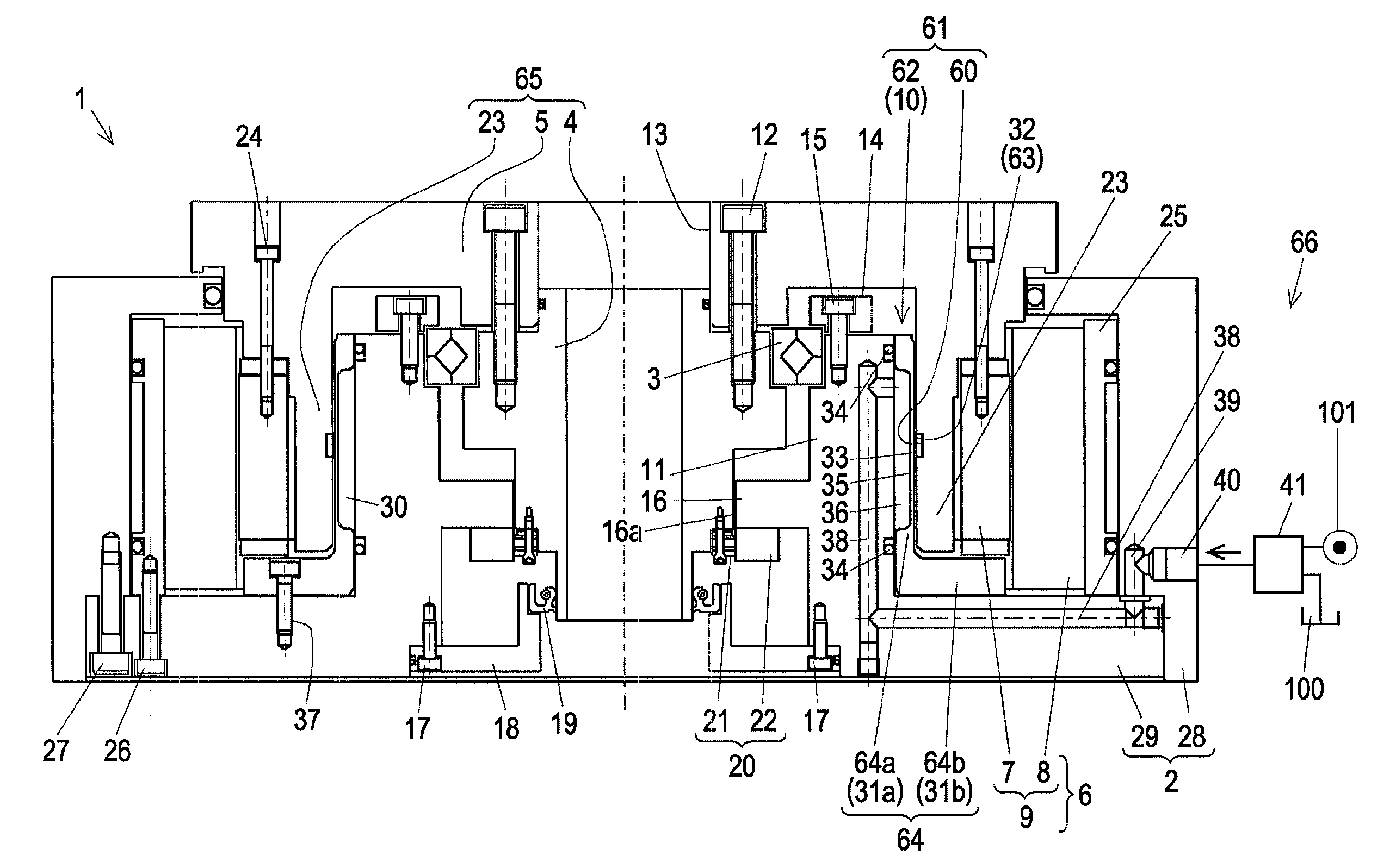
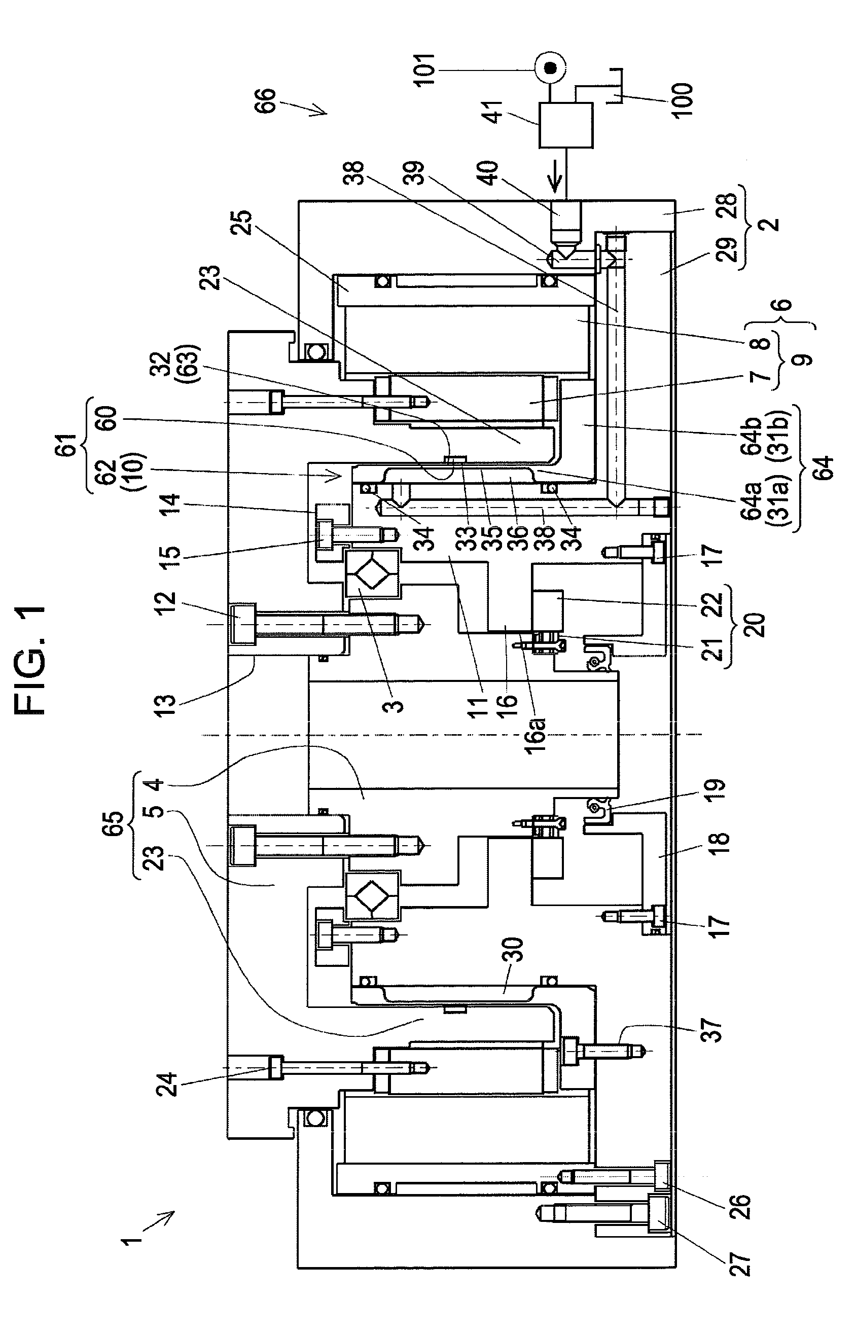
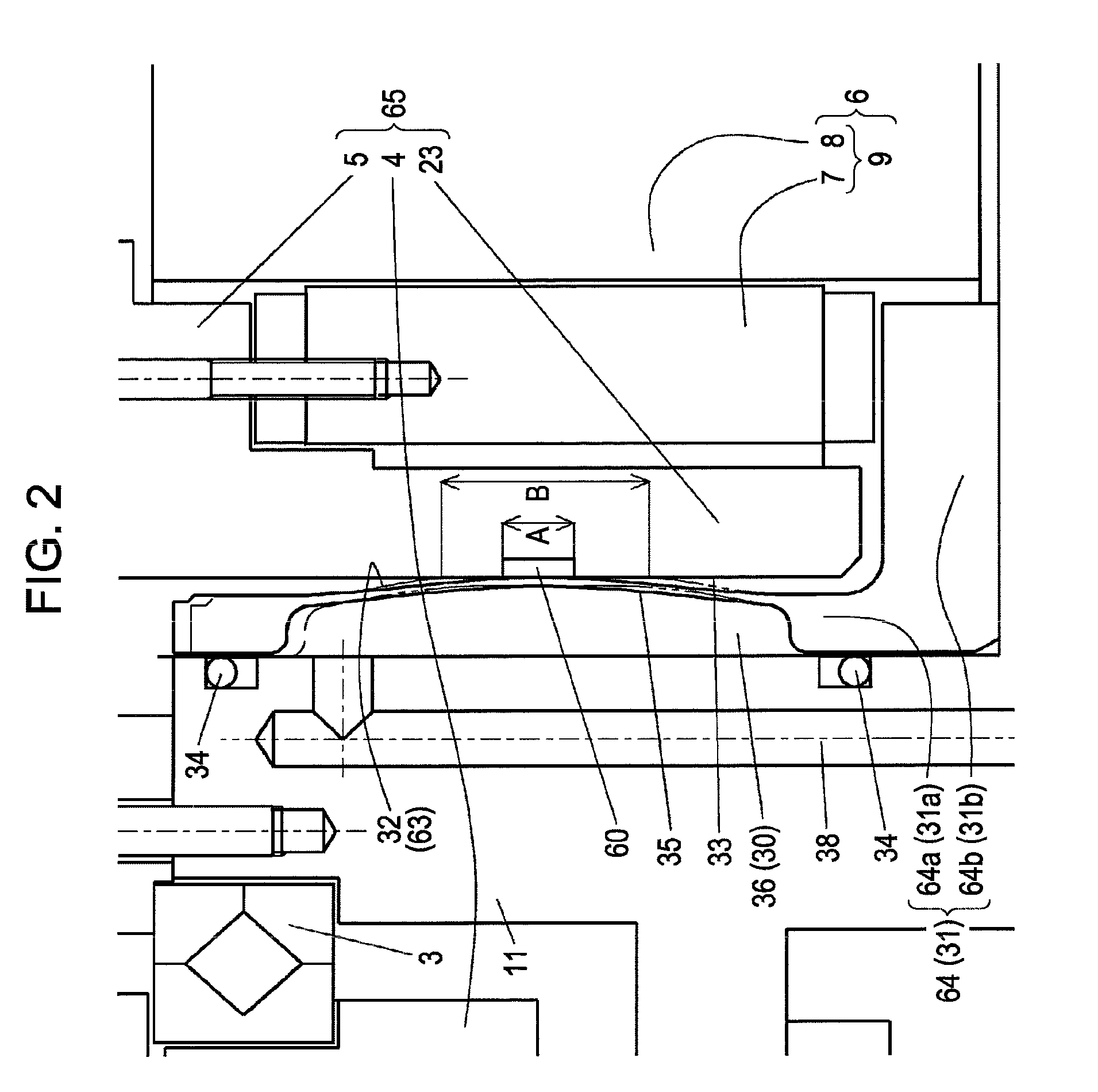
[0108]FIGS. 1 and 2 show a rotation index table device 1 as a main shaft drive for a machine tool according to the present invention. FIG. 1 is an overall view thereof. In the description below, “axial direction” refers to the direction of an axis of a main shaft 4 that supports a circular table 5 serving as a rotationally driven member, and “radial direction” refers to a radial direction of the main shaft 4, the circular table 5, and a DD motor 9 that are concentrically disposed.

[0109]In FIG. 1, the rotation index table device 1 includes a rotating body 65 and a driving device 6. The rotating body 65 includes the main shaft 4, supported by a bearing 3 so as to be rotatable with respect to a frame body 2, and the circular table 5, secured to an end portion of the main shaft 4. The driving device 6 rotationally drives the rotating body 65. A portion of the frame body 2 that becomes a setting surface with respect to the machine tool is a flat surface. The frame body 2 has a cylindrica...


PUM


Abstract

When a finishing operation is performed while rotating a workpiece at a main shaft drive of a machine tool, pulsation occurring in a rotation of the main shaft drive is restricted and the rigidity of a main shaft is increased without increasing the size of a bearing. A rotation-resistance device of a main shaft drive in a machine tool has the following structure in the main shaft drive including a main shaft 4, a rotating body 65, and a driving device 6, the main shaft 4 being supported so as to be rotatable with respect to a frame body 2, the rotating body 65 being secured to an end of the main shaft 4, the driving device 6 rotationally driving the rotating body (65). The rotation-resistance device includes a damping device (10) including a damping member, which is provided at the frame body 2 or the rotating body 65 and which includes a resiliently deformable damping section, a pressing-force applying device 66, which applies a pressing force to the damping member by operating fluid, and a damping surface 32, provided at a side of the frame body 2. The damping device 10 causes the pressing force to act upon the damping section to flex the damping section, so that the damping surface 32 and a sliding surface 33 are pressed against each other, and a rotation resistance that allows rotation is applied to the rotating body 65. A low-friction coefficient member 60 is secured to at least one of the damping surface 32 and the sliding surface 33.

Description

TECHNICAL FIELD[0001]The present invention relates to a main shaft drive in a machine tool, in which a main shaft, supported so as to be rotatable with respect to a frame body, and a rotationally driven member, which is secured to an end portion of the main shaft, is rotationally driven by a driving device.BACKGROUND ART[0002]One related art regarding the main shaft drive in the machine tool is discussed in Patent Document 1. The main shaft drive in the machine tool in Patent Document 1 is a rotation index table device, and uses, as driving means of the main shaft, a direct drive motor (what is called a “DD motor”) that rotationally drives the main shaft without using drive transmission means such as a gear.[0003]In the rotation index table device in the aforementioned Patent Document 1, a clamped / unclamped state of a table is switched by introducing operating fluid. When a piston is constantly urged towards a brake plate by a compression spring and the introduction of the operating...

Claims


Application Information

Patent Timeline
Patent Type & Authority Applications(United States)
IPC IPC(8): B23Q16/06F16D55/10
CPCB23Q16/107B23Q2220/004Y10T74/1453B23Q11/0032B23Q11/0025
Inventor TATSUDA, YOSHINORI
Owner TSUDAKOMA KOGYO KK
Why Eureka
Try Eureka