Driver device for leds

Inactive Publication Date: 2011-02-03
KONINKLIJKE PHILIPS ELECTRONICS NV
View PDF7 Cites 60 Cited by
  • Summary
  • Abstract
  • Description
  • Claims
  • Application Information

AI Technical Summary

Benefits of technology

[0014]In another embodiment of the electroluminescent device, the LEDs of different switching units are able to provide light of different colors.

Problems solved by technology

It is especially suited for applications where the current flow of each LED in a string has to be varied and PWM-dimming is not suitable (where no PWM-based light output modulation is wanted).

Method used


Image

  • Driver device for leds
  • Driver device for leds

Examples


Embodiment Construction

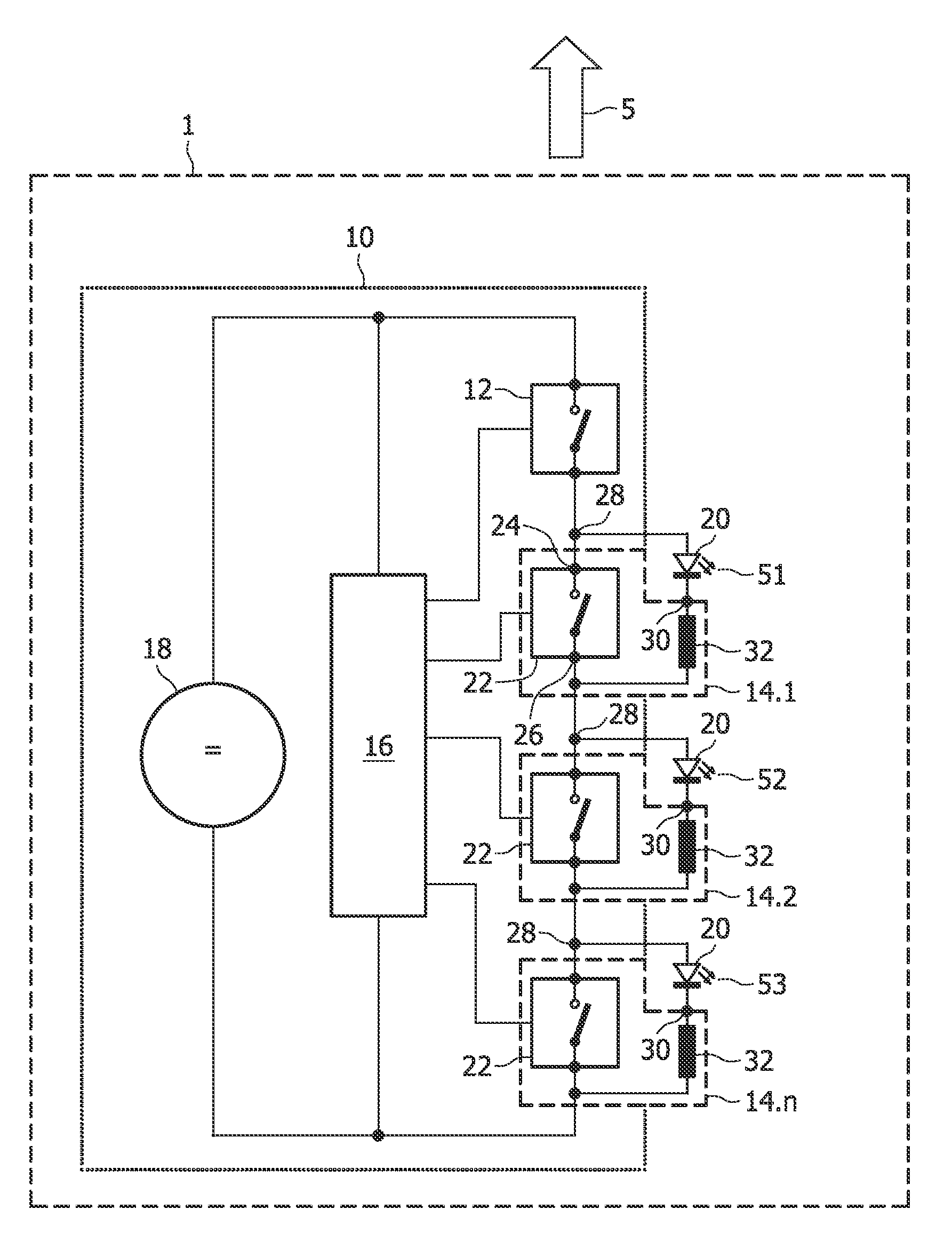
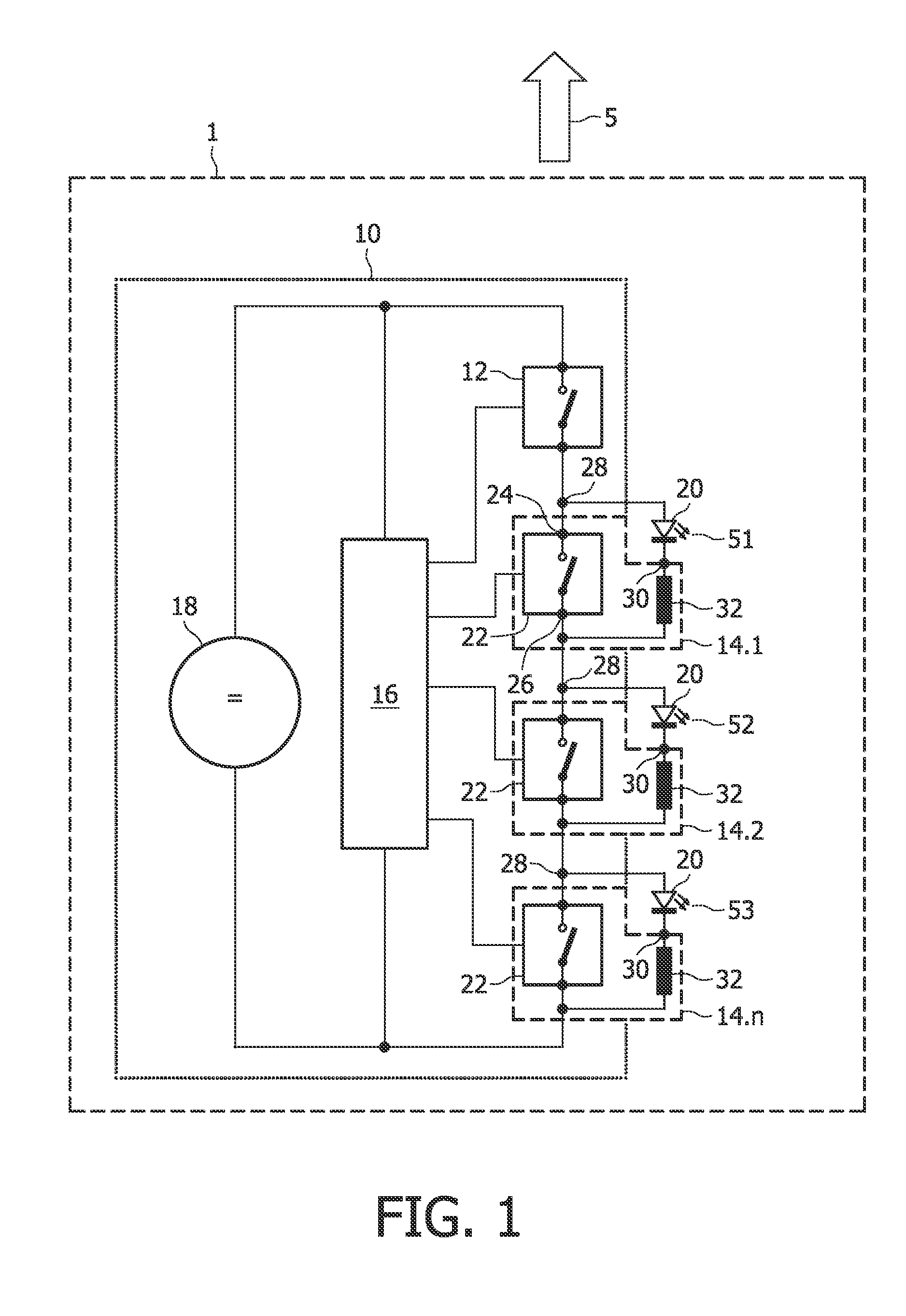
[0025]In FIG. 1, a driver device 10 for light emitting diodes is schematically shown and indicated with reference numeral 10. The driver device 10 comprises a main switch 12 and a plurality of switching units 14.1 to 14.n. The main switch 12 and the switching units 14 are connected in series and are coupled with a DC-power supply 18.

[0026]Further, the driver device 10 comprises a control unit 16 receiving power from the power supply 18 and being adapted to control the main switch 12 as well as the switching units 14. As an alternative, the control unit could receive power from a tap to some position in the Led string (not shown in FIG. 1).

[0027]The structure of each switching unit 14.1 to 14.n is similar so that only one switching unit 14.1 will be explained in more detail below.

[0028]The switching unit 14.1 comprises a switch 22, for example an electronic switch, like a transistor, or any other controllable switch, which has a first end 24 connected to the main switch 12 (or the pr...


PUM


Abstract

The present invention relates to a driver device (10) for driving and controlling light emitting diodes (LEDs) or LED-strings comprising a control unit (16), and at least two switching units (14) coupled in series, and each comprising a switch (22) controllable by said control unit (16) and two connection points (30) for connecting at least one LED, wherein the first connection point (28) is coupled with one end of said switch (22). The driver device is characterized in that each switching unit (14.1 to 14.n) comprises an inductance coupled between the other end of said switch (22) and said second connection point (30).

Description

FIELD OF THE INVENTION[0001]The present invention relates to a driver device for driving and controlling light emitting diodes (LEDs) or LED-strings / arrays comprising a control unit, an electroluminescent device comprising the driver device and LEDs or LED-strings / arrays connected to the driver device to emit mixed light and a method for operating the electroluminescent device in order to adjust brightness and / or color point of the emitted mixed light.BACKGROUND OF THE INVENTION[0002]Driver devices for driving light emitting diodes are generally known, for example from document U.S. Pat. No. 6,153,980.[0003]Generally, LEDs are currently in wide spread use in a variety of different signaling and lighting applications and LED-based luminary products. To increase the application field of LED-based luminaire products, LEDs with different colors (or CCT in case of white LEDs) can be used to generate light of a desired color. To achieve this, the average light output of the LEDs are set t...

Claims


Application Information

Patent Timeline
Patent Type & Authority Applications(United States)
IPC IPC(8): H05B37/02H05B44/00
CPCH05B33/0818Y02B20/346H05B33/083H05B45/48Y02B20/30H05B45/20H05B45/3725
Inventor SCHULZ, VOLKMARRADERMACHER, HARALD J.G.
Owner KONINKLIJKE PHILIPS ELECTRONICS NV
Why Eureka
Try Eureka